


23
23
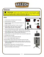
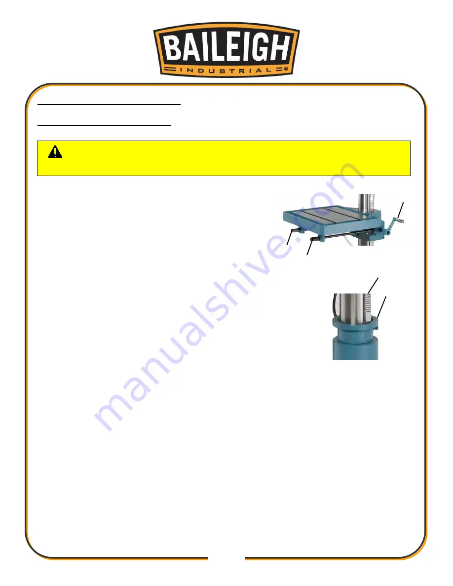
SET UP AND ADJUSTMENTS
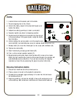
Adjusting the Gear Rack Height
1. Raising the table to an adequate working height may
require raising the column gear rack.
2. Lock the table by turning crankshaft (I) clockwise (cw).
3. Raise the gear rack (G) by turning either crankshaft (F)
counterclockwise (ccw).
4. Unlock column bearing (Y) by loosening the two
setscrews and sliding it up to the gear rack.
5. Lock column bearing (Y) by tightening the two setscrews.
6. After unlocking (I), the table can now be raised or lowered for
normal operation.
CAUTION:
Failure to lock the collar can result in personal injury or
damage to the machine.
F
F
I
Y
G
Содержание DP-1000VS
Страница 19: ...16 16 OVERALL DIMENSIONS ...
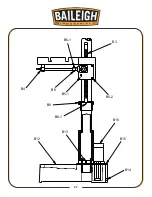
Страница 20: ...17 17 GETTING TO KNOW YOUR MACHINE Q F P J B C A G H I L M E F D N O K R ...
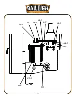
Страница 35: ...32 32 A6 2 A6 3 A6 1 A6 4 A8 1 A8 2 A5 A5 1 A33 1 A19 1 A33 ...
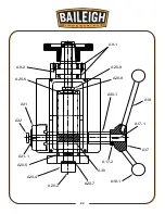
Страница 36: ...33 33 A20 7 A30 A17 2 A17 1 A17 A18 A18 1 A30 1 A20 9 A20 8 A9 1 A9 2 A20 6 A31 A32 A31 1 A20 5 A20 4 A20 2 ...
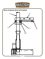
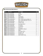
Страница 39: ...36 36 BASE COLUMN AND TABLE PARTS DIAGRAM B1 B2 B11 B10 B9 B10 1 ...
Страница 40: ...37 37 B3 B4 B6 1 B6 B5 1 B5 2 B8 B8 1 B12 B13 B16 B15 B14 ...
Страница 44: ...41 41 COOLANT PUMP ASSEMBLY PARTS DIAGRAM ...
Страница 46: ...43 43 CONTROL PANEL PARTS DIAGRAM ...
Страница 48: ...45 45 CHUCK GUARD PART DIAGRAM ...
Страница 51: ...48 48 ELECTRICAL ENCLOSURE COMPONENTS ...