


25
25
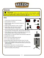
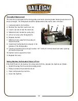
Tapping
1. Load and secure the piece part to the table.
1. Secure tapping tool in the chuck.
2. Unlock the table, adjust to the desired height, and
relock the table.
3. Adjust the safety guard up or down as needed.
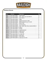
4. Selector switch (A) shown in tapping position.
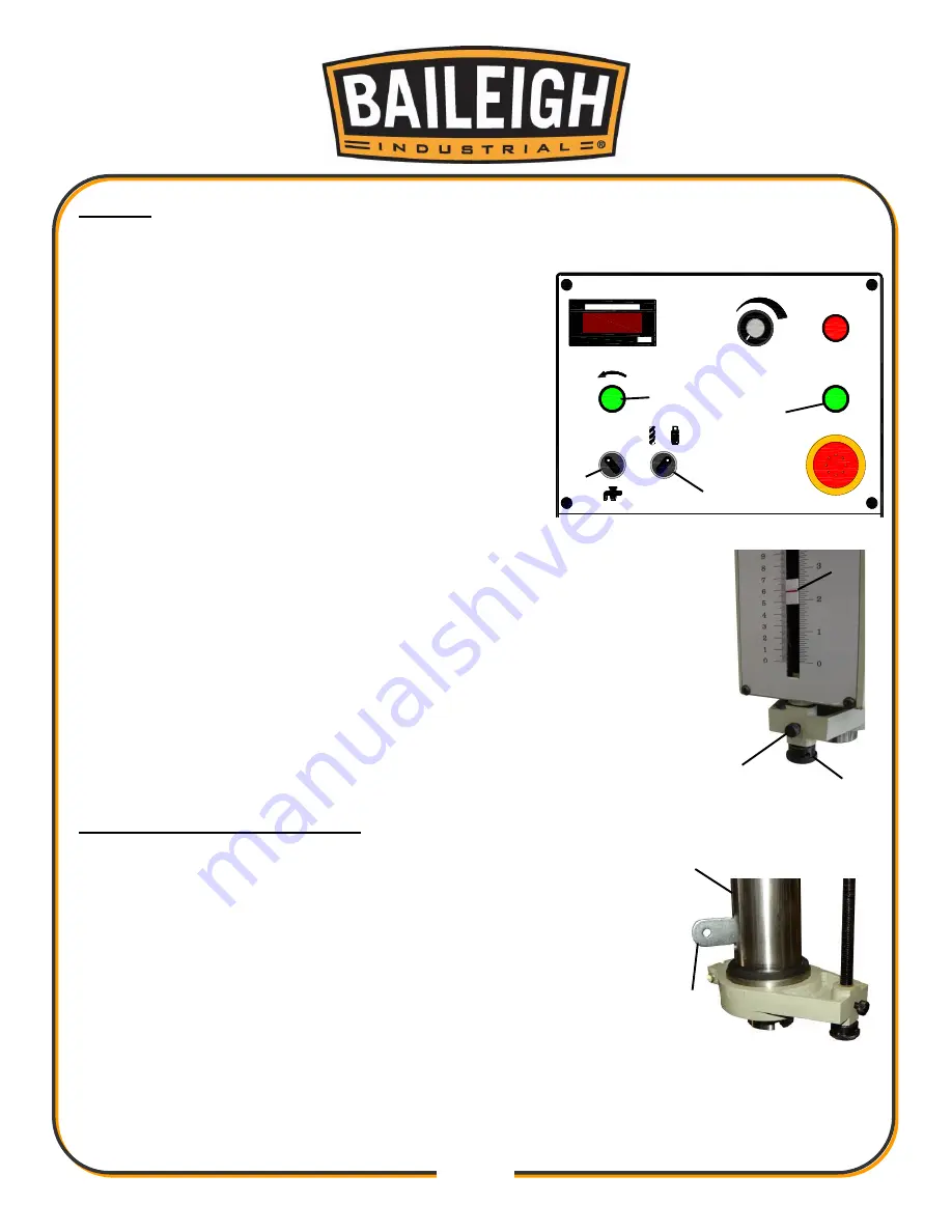
5. Set the tap tool depth to zero position by lowering it
to the top surface of the piece part, using the down-
feed handles.
6. While holding the zero position, turn the depth scale
lock knob (B) counterclockwise (ccw) to release depth stop knob (C).
7. Rotate knob (C) to set the drill depth on the scale with indicator (D).
8. Tighten lock knob (B).
9. Start machine by pressing start button (E)
10. Turn on the coolant selector switch (F).
11. Begin tapping using the down-feed handles (E) to lower the chuck.
When the tap reaches the bottom of the preset depth, the spindle will
automatically reverse direction. You can also reverse the tapping
operation at any time by pressing the green reverse button (G).
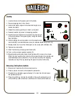
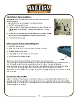
Removing Tooling from Spindle
1. Disconnect machine from the power source.
2. Place a piece of wood on the table for protection.
3. Position the worktable approx
imately 10” under the bit and lower
the spindle about 6”.
4. Place the drift key (A) into the slot (B) of the quill and tap the end
of the drift key with a hammer until the bit or chuck arbor falls out.
C
B
D
A
B
DIGITAL INDICATOR
RPM
0
l
150-3000RPM
0
l
SPINDLE SPEED
E
G
F
A
Содержание DP-1000VS
Страница 19: ...16 16 OVERALL DIMENSIONS ...
Страница 20: ...17 17 GETTING TO KNOW YOUR MACHINE Q F P J B C A G H I L M E F D N O K R ...
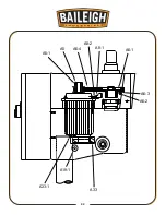
Страница 35: ...32 32 A6 2 A6 3 A6 1 A6 4 A8 1 A8 2 A5 A5 1 A33 1 A19 1 A33 ...
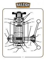
Страница 36: ...33 33 A20 7 A30 A17 2 A17 1 A17 A18 A18 1 A30 1 A20 9 A20 8 A9 1 A9 2 A20 6 A31 A32 A31 1 A20 5 A20 4 A20 2 ...
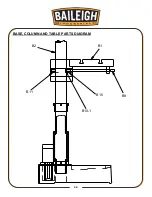
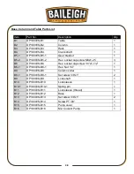
Страница 39: ...36 36 BASE COLUMN AND TABLE PARTS DIAGRAM B1 B2 B11 B10 B9 B10 1 ...
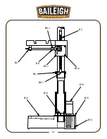
Страница 40: ...37 37 B3 B4 B6 1 B6 B5 1 B5 2 B8 B8 1 B12 B13 B16 B15 B14 ...
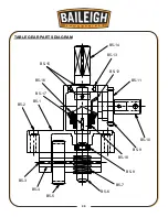
Страница 44: ...41 41 COOLANT PUMP ASSEMBLY PARTS DIAGRAM ...
Страница 46: ...43 43 CONTROL PANEL PARTS DIAGRAM ...
Страница 48: ...45 45 CHUCK GUARD PART DIAGRAM ...
Страница 51: ...48 48 ELECTRICAL ENCLOSURE COMPONENTS ...