Baby Lock Kinetic Frame Assembly Instructions 15
Fig. 5-1
QF09318-02
Fig. 5-2
QF09318-02
Fig. 5-3
QF09318-02
Fig. 5-4
QF09318-02
Step 7
Track Assembly
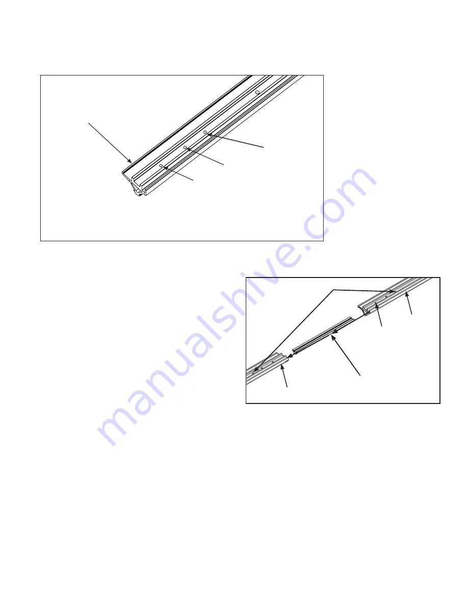
7-3: To prepare for joining the sections
together, screw one M5x8mm QF09318-304
into the third hole from the splice end of each
section to serve as a stop screw. (Figs. 7-1,
7-2) Fully tighten the screw with the 3mm
Allen wrench. This will help align the coupler
properly into the two track support sections
when joined.
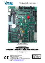
7-4: Insert a coupler into one prepared end of
one track support section up to the stop screw.
Thread an M5x8mm QF09318-304 into the first
and second hole and lightly tighten as shown
in Fig. 7-2.
Parts needed
(1) frame assembly
(4) track support
(2) track support couple
(12) M5x8mm Socketed Button Head
Cap Screw QF09318-304
(12) M6x12mm Socketed Washer Head Cap
Screw QF09318-303
(4) Black Track
Tools Required
3mm Allen wrench (provided)
4mm Allen wrench (provided)
7-1: Place the four (4) track supports, removed
earlier, on the frame assembly top with the
screw holes up and the wide lip of the supports
facing the outside of the table.
(Fig. 7-1)
7-2: Check inside the ends of the track
supports for burrs or debris and remove all
foreign matter from the inside.
Track Support shown upside down.
Second Hole
Place the track support
upside down with the lip
toward the outside of the
table.
First Hole
Third Hole for
stop screws
Stop Screws M5 x 8mm SBHCS QF09318-304
in Third Hole
End Section
Fig. 7-1
Fig. 7-2
End Section
Coupler
First Hole
Содержание Kinetic Frame
Страница 1: ......


