background image

B9 Scan 500 Operating Manual 


Page29 

Item


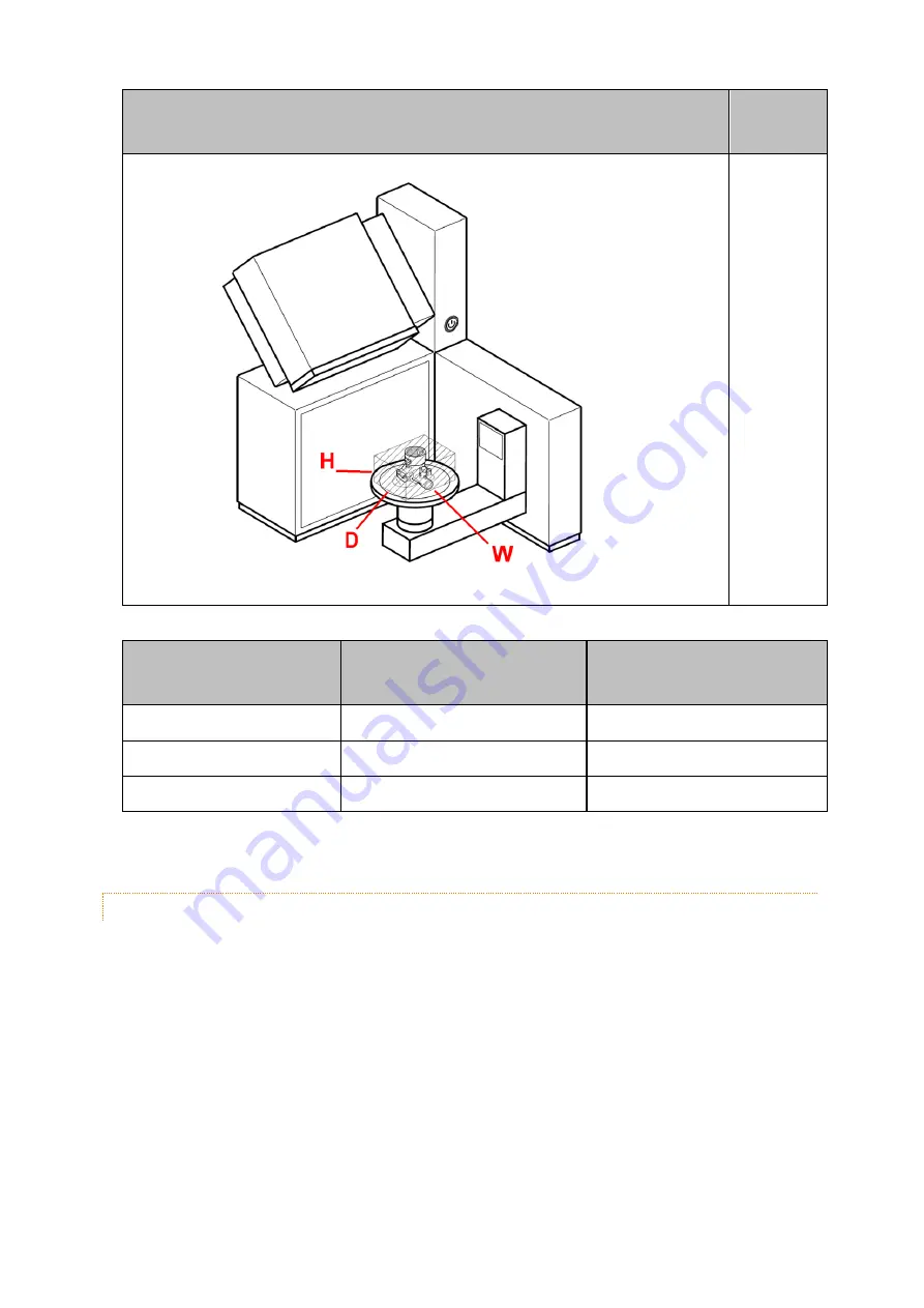
W x D x H


[mm]


90 x 60 x 55


The spacer helps to manage models with different height. The below table is suggested.


Model


Max model height


[mm]


Spacer


Normal size


50


Long spacer


High


70


Short spacer


Very high


90


No spacer


In the following paragraph more detailed instruction


8.3.1.1.


STANDARD MODEL PLACEMENT 

Properly placing a single model requires the use of the working plate included in the "

AP-

0000015 Model plate kit"

. If the model is less 50 mm height, follow the below procedure:


1.


Attach a model on the working plate like described in the "AP-0000015 Model plate kit 
Operating Manual"


2.


Secure the working plate on the long spacer by aligning the keys.


Содержание B9 Scan 500

Страница 1: ...B9 Scan 500 Operating Manual...

Страница 2: ...information 6 3 Use in accordance with specifications 9 3 1 Working rules 9 4 Scope of delivery consumables set 10 4 1 Scope of delivery 10 4 2 Basic equipment set 11 4 3 Additional accessories 11 5...

Страница 3: ...9 3 System Configuration 36 10 B9 Scan User s Guide 37 11 Maintenance 38 11 1 Routine maintenance 38 11 1 1 Maintenance and care 38 11 1 2 Dust filter cleaning 39 11 2 Fuses replacing 41 11 3 Software...

Страница 4: ...light technology It has an open casing configuration and it can handle big size models B9 Scan 500 has an integrated PC installed inside scanner casing It is completely PLUG PLAY requiring only a mon...

Страница 5: ...n within the working instructions on the opti mum use of the unit WARNING This symbol warns of the dangers of electric voltage DISCONNECT FROM MAINS Danger of electric shock when unit is opened Unplug...

Страница 6: ...TION Prior to operation read the B9 Scan 500 Operating Manual carefully adhere to the infor mation provided in order to avoid errors and damage in particular damage to the health In addition to the in...

Страница 7: ...used The use of different parts holds un known risks and must be avoided at any rate Proper function and safety of the unit are only guaranteed if the required tests maintenance and repair work have b...

Страница 8: ...power unit removing the scanner cover Works at the elec trical equipment of the unit must only be performed by the authorized E G S srl service agents and in the safe condition voltage cleared Please...

Страница 9: ...re difficult to acquire Coating the surfaces with a thin opaque lacquer just for measuring purposes is a common practice Transparent or semi transparent surfaces raise difficulties too Also in these c...

Страница 10: ...t all components are in perfect condition upon delivery of the machine If you wish to make a complaint contact your supplier 4 1 SCOPE OF DELIVERY Item Q ty Description 1 Accessories box 1 Additional...

Страница 11: ...cessories box Item Q ty Description 1 Calibration plate 1 Short spacer 1 Power cord 1 DVI I cable 1 HDMI 90 adapter 2 Fuse T 5A 250V 1 2 5 mm hexagonal tool 4 3 ADDITIONAL ACCESSORIES Item Code Descri...

Страница 12: ...B9 Scan 500 Operating Manual Page12 Item Code Description Leios 2 R10 Contact our service agents for any additional information See paragraph Service...

Страница 13: ...ICATION The product plate is on the scanner rear panel Item B9 Scan 500 A Company Product Label Product type Serial Number Prod uct year Rating Weight NOTE In any request for technical assistance alwa...

Страница 14: ...00 Operating Manual Page14 Item B9 Scan 500 A On Off switch B Long spacer C Coupling system D Main On Off AC switch E Fuses F AC Socket G USB 2 0 Ports H Ethernet Ports I USB 3 2 Ports J DVI I Port K...

Страница 15: ...agraph Technical data 6 2 UNPACKING The B9 Scan 500 device is shipped inside a cardboard box 1 Open the upper side of the cardboard box at the position where the clamps are present 2 Open the protecti...

Страница 16: ...500 Operating Manual Page16 Take care not to pinch your fingers when placing the scanner on the table NOTE It is suggested to keep the packaging in case you need to ship the scanner for technical ass...

Страница 17: ...obstacle because it is en gaged by the mova ble tray during ac quisition CAUTION This symbol warns about the dangers of risk of trapping hands fingers 270 x 290 The scanner needs to be positioned with...

Страница 18: ...er prior to acclimatization 7 1 HARDWARE SETUP To properly setup the hardware follow the below steps Item B9 Scan 500 Connect the mouse and the keyboard using USB 2 0 ports in the scanner back panel I...

Страница 19: ...B9 Scan 500 Operating Manual Page19 Item B9 Scan 500 Connect the DVI I cable to the vertical scanner DVI I port and plug it into the monitor DVI I port The monitor is not included in the package...

Страница 20: ...onitor mains cable is not provided in the package CAUTION 1 Mains 100 240 Vac 50 60 Hz 2 Do not use any type of extension cord 3 Do not connect the de vice to any type of backup generator Connect the...

Страница 21: ...ational The license activation takes place at the end of the user registration operations to be performed at the first launch of the product 1 Double click on the B9 Scan icon in the desktop 2 Push RE...

Страница 22: ...owed with the machine are Operations On Off Setting Acquisition Model1 Putting into operation Reset tray position Normal size Putting out of operation Coupling spacer High Calibration Very high 1 The...

Страница 23: ...r will be in idle mode ready for the operations The PC monitor will show the standard Windows desktop page On the left side there is the icon belonging to B9 Scan application See B9 Scan User s Guide...

Страница 24: ...Scan icon in the desktop 2 Click on Action menu Scanner Reset tray position or directly double click on icon 3 Wait until a dialog box confirms the end of the process In a few seconds the plate will...

Страница 25: ...spacers a long one A mounted by default on the scanner and a short one B To execute some operations or using accessories the long spacer must be removed If re quired apply the following procedure 1 Re...

Страница 26: ...acer always with the retention screw 8 2 3 CALIBRATION The B9 Scan 500 calibration procedure is a very simple task 1 Put the calibration plate directly on the long spacer 2 Double click on the B9 Scan...

Страница 27: ...If the scanner is not moved and kept at a constant temperature it can be calibrated once every two weeks Calibration is always necessary when o The first time the scanner is unpacked o When the scanne...

Страница 28: ...m the points into a mesh NOTE The scanning process can be interrupted any moment by clicking the button Stop the scanner immediately stops moving and all the the data are lost Use a Reset tray positio...

Страница 29: ...90 No spacer In the following paragraph more detailed instruction 8 3 1 1 STANDARD MODEL PLACEMENT Properly placing a single model requires the use of the working plate included in the AP 0000015 Mode...

Страница 30: ...Opera tions Coupling spacer 2 Use the short spacer coupling it directly to the coupling system 3 Secure the working plate on the short spacer 8 3 1 3 VERY HIGH MODEL PLACEMENT If the model is more th...

Страница 31: ...B9 Scan 500 Operating Manual Page31...

Страница 32: ...tomer service 2 The scanner is On but nothing is visible on the monitor DVI I cable non properly con nected to the DVI I port in the scanner Use the right DVI I port in the scanner DVI I cable not wo...

Страница 33: ...een moved from its position or shaken Reset tray position The acquisition process has stopped The B9 Scan application crashed during acquisition The scanner was turned off by us ing the front On Off s...

Страница 34: ...ibration process was not correctly run Calibrate the scanner A USB Webcam or HUB is installed Remove the Webcam or the HUB If none of the above solves the problem contact E G S srl cus tomer service 1...

Страница 35: ...ration plate damaged or scratched Replace the calibration plate Wrong spacer used Use long spacer If none of the above solves the problem contact E G S srl cus tomer service 14 The B9 Scan application...

Страница 36: ...and hardware settings If an error is detected the dialog box of the Configuration Control Panel will be shown Depending on the errors detected some items will be active EDIT button it opens a dialog b...

Страница 37: ...B9 Scan 500 Operating Manual Page37 10 B9 SCAN USER S GUIDE See the B9 Scan User s Guide manual for further details Double click on the B9 Scan icon on the desktop select Main menu User Guide...

Страница 38: ...ted there see paragraph Service 11 1 ROUTINE MAINTENANCE The B9 Scan 500 periodic maintenance operations are Maintenance Action D W M 3M 6M 12M Maintenance and Care Cleaning Cover Plate Cleaning Camer...

Страница 39: ...ur liquids directly onto the scanner Do not use an excessively wet cloth or allow water getting inside the case Do not use any abrasive cleaners Do not use solvents such as acetone isopropyl alcohol h...

Страница 40: ...direction 5 Use a blow of low pressure compressed air to clean it Direct the air blow as shown in the figure If necessary replace the entire filter DISCONNECT FROM MAINS Always disconnect the equipmen...

Страница 41: ...erious injury WARNING Always replace a fuse with an identical type and never substitute a fuse with foil or an other object This could lead to electrocution and fires Do not keep replacing a fuse if i...

Страница 42: ...pare parts must be used The use of different parts holds unknown risks and must be avoided at any rate NOTE The B9 Scan 500 is provided with all the software required for the operations If additional...

Страница 43: ...arliament and the European Council of 2005 05 03 Its main purpose is to prevent waste from electrical and electronic equipment and to promote reuse recycling and other forms of recovery to reduce both...

Страница 44: ...axis movement Rotation Tilting Max model size W x D x H 180 x 180 x 180 mm Max model weight 1 8 Kg 3D scanning volume W x D x H 90 x 60 x 55 mm Accuracy 0 010 mm Input data format STL ASC PLY OBJ Out...

Страница 45: ...B9 Scan 500 Operating Manual Page45 Specifications B9 Scan 500 Package weight 24 Kg...

Страница 46: ...X HDMI 1 X DVI D 2 X USB 3 2 2 X USB 2 0 1 X Ethernet 10 100 1000 Mbps OS Windows 10 Pro 64 bit 14 1 OPERATING CONDITIONS Specifications B9 Scan 500 Use only indoors Temperature range 10 C to 40 C Re...

Страница 47: ...B9 Scan 500 Operating Manual Page47 Model Company Product Label B9 Scan 500 14 3 DIMENSIONS...

Страница 48: ...B9 Scan 500 Operating Manual Page48 14 4 ELECTRICAL CIRCUIT DIAGRAM...

Страница 49: ...B9 Scan 500 Operating Manual Page49 15 OPERATIONS CHECK LIST Putting into operations...

Страница 50: ...ick Main menu Calibration 4 Click the OK button in the Calibration Mode dialogue box 5 Wait a few minutes until a dialogue box confirms the end of the process Acquisition 1 Place properly the model or...

Страница 51: ...B9 Scan 500 Operating Manual Page51 2 Turn off the scanner bt using either the Shutdown button in the desktop Start menu or the front switch button...

Страница 52: ...500 Operating Manual Page52 16 SERVICE Service Partners E G S srl Via del Tappezziere 4 40138 Bologna BO Italy Tel 39 0 5119930101 Fax 39 0 5119900892 Email egs info egsolutions com Web www egsolutio...

Страница 53: ...ition Date Comments DC 0000171 0 27 11 2019 Emission DC 0000171 A 23 11 2020 Update due to LumenD minor fixes DC 0000171 B 05 02 2021 Updated technical data e minor bugs fixed DC 0000171 C 09 04 2021...

Страница 54: ...B9 Scan 500 Operating Manual Page54 KEYWORD INDEX No index entries found...

Отзывы: