___________________________________________________H3000 Pilot Handbook
HB-3001-02
79
Network Installation
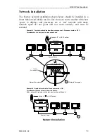
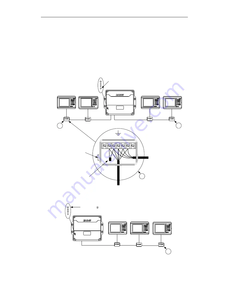
The Fastnet network installation shown below should be installed in a
linear fashion and ideally run in a line from one end to another with short
‘spurs’ to displays and processors etc. A ‘star’ network with many
network spurs off one point will not work correctly, and must be
avoided.
Switch to "0" = (OFF Position)
T
T
Switch to " " = (ON Position)
T
T = Network Terminator
G W Scn Blk R
Processor
Processor
Fastnet Cable
Fastnet Cable
Example 1: Two network cables from the processor unit. Processor switch = OFF.
Terminated in the last junction box at each end
Example 2: Single network cable. Processor swich = ON
Terminated at processor unit via switch shown.
Add a network terminator to the last junction box at the end.
Network Terminator
Insert
Grommet Plug
Network Installation
Содержание H3000 Pilot
Страница 1: ...Pilot Handbook www bandg com ...
Страница 106: ......
Страница 115: ...___________________________________________________H3000 Pilot Handbook HB 3001 02 9 Type 1 and 2 Ram Drive Dimensions ...
Страница 117: ...___________________________________________________H3000 Pilot Handbook HB 3001 02 11 Type 3 Ram Drive Unit Dimensions ...
Страница 118: ...H3000 Pilot Handbook___________________________________________________ HB 3001 02 12 Type 3 Ram Bolt Detail ...


