AV6A
1
w w w. a v t r o n e n c o d e r s . c o m
2 4 3 Tu x e d o A v e n u e | C l e v e l a n d , O h i o 4 4 1 3 1
e n c o d e r h e l p d e s k @ n i d e c - i n d u s t r i a l . c o m | + 1 2 1 6 - 6 4 2 - 1 2 3 0
Nidec Makes the Most Reliable Encoders in the World
Encoder Instructions
MODEL
AV6A
ABSOLUTE OPTICAL
SOLID SHAFT ENCODER
DESCRIPTION
The Avtron Model AV6A is a light mill duty absolute encoder. It
expresses the position of rotation as an output message or value.
AV6A can measure a single turn of rotation or multiple rotations. The
AV6A measures the shaft rotation and position without the need for
external power or internal batteries or capacitors through its multi-
turn gear system. The AV6A operates down to zero speed and can be
used for both control and instrumentation applications.
CAUTION
Do not utilize AV6A in hazardous locations which
require ATEX, UL, CUL, CSA, or other explosion protection
certification. AV6A is not certified for hazardous
locations.
The AV6A is designed for mounting on flanges (58mm, 36mm,
1.25”), or on a foot mount bracket for coupling. The AV6A is not
recommended for pulley or chain drive applications.
SAFETY
The AV6A is not considered as a safety device and is not suitable for
connection into a safety system.
WARNING
Installation should be performed only by qualified
personnel. Safety precautions must be taken to ensure
machinery cannot rotate and all sources of power are
removed during installation.
INSTALLATION
Refer to the back page of these instructions for outline and mounting
dimensions.
Equipment needed for installation
Supplied:
AV6A Encoder
Optional:
(none)
Not Supplied:
Open Wrenches, Hex Wrenches, Dial Indicator Gauge
Caliper Gauge, Coupling, Foot Mount and Mounting Screws
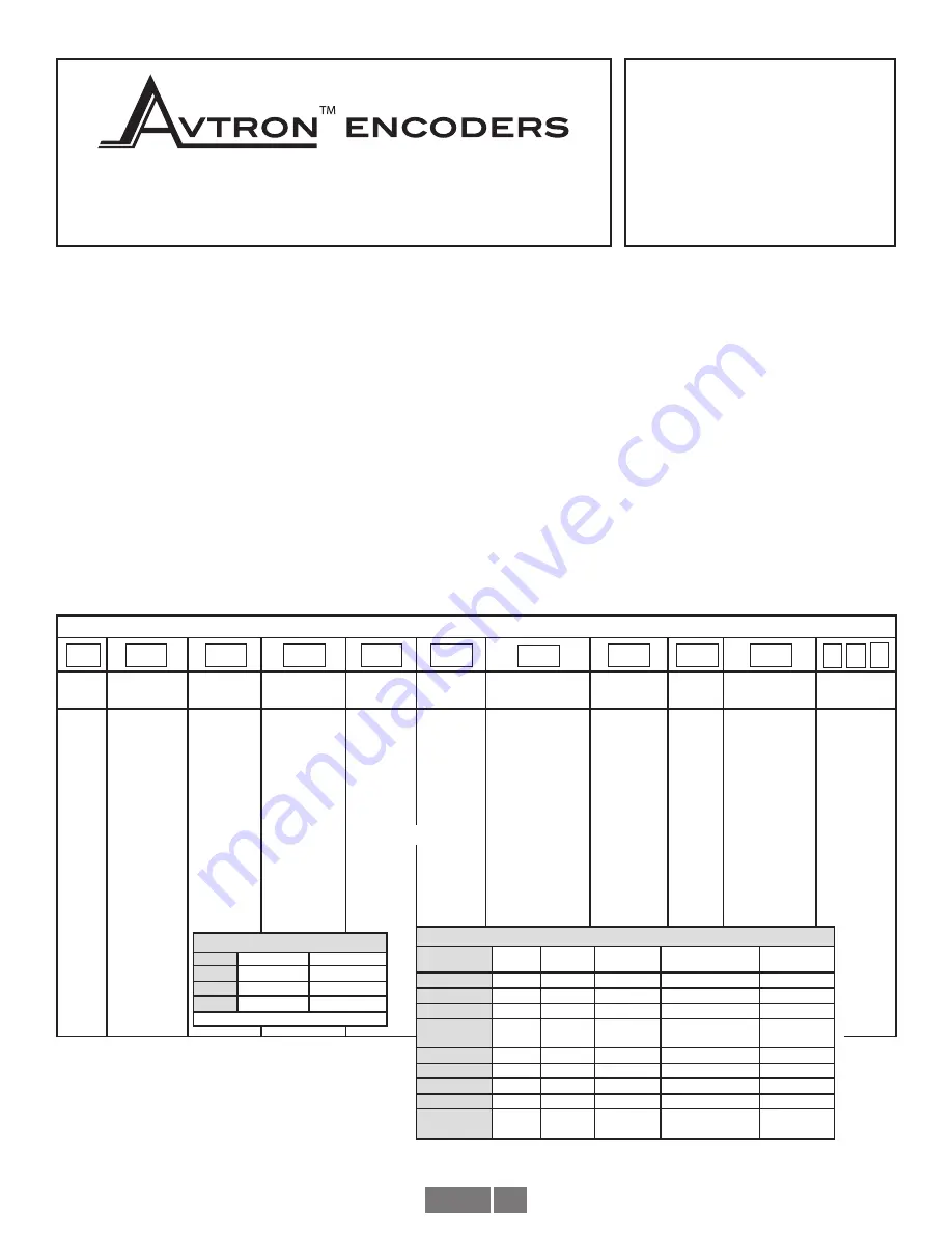
AV6A PART NUMBERS AND AVAILABLE OPTIONS
Model
Bus
Flange
Shaft Size
Turns/
bits
PPR/bits
per turn
Connector Connector
Exit
Output
IP
Rating
Special
Option
AV6A
C-
CANOpen
D-
DeviceNet
K-
POWERLINK
L-
Parallel
M-
ModbusTCP
Ethernet
N-
Profinet IO
P-
Profibus DP
R-
Ethernet/IP
S-
SSI
1-
58mm “servo/
clamp” flange,
36mm male
pilot, 3X M3,
3X M4 at
48mm
2-
58mm
“synchro”
flange, 50mm
male pilot,
3X M4
at 42mm
4-
2.5” square
flange
w/1.25” male
pilot
B-
3/8” dia. x
5/8” w/flat
C-
10mm dia. x
20mm w/flat
T-
6mm dia., x
10mm, no flat
X-
0/0-
single turn
A-
16/4**
D-
128/7**
E-
256/8**
2-
4096/12
4-
16384/14
E-
256/8**
F-
512/9**
0-
1024/10**
2-
4096/12
3-
8192/13
4-
16384/14
6-
65536/16
A-
1xM12/5 pin
B-
2xM12/5 pin
C-
3xM12 4/4/5
or 4/4/4 pins
D-
2xM12/4/5 pin
E-
M12/8 pin
F-
M23/12 pin
G-
M27/26pin
J-
2x cable entry
K-
3x cable entry
M-
M23/8pin Hengstler
N-
M23/8pin Stegmann
Q-
M23/8pin Kubler
W-
Cable, 1m
A-
side/radial
E-
end/axial
1-
Binary
2-
Gray
X-
None, IP54
+
A-
IP66 shaft seals
S-
IP66 seals,
stainless
housing
000-
none
9xx-
special cable
length
xx=length
*0.3m
FLANGE COMPATIBILITY
Flange
Shaft
IP/Sealing
1
C
X
+
, A, S
2
C, T
X
+
, A, S
4
B
X
+
, A, S
+
X - no seal option not recommended
STANDARD CONNECTORS & OUTPUT FORMATS
Bus
Code
Turns/
Bits*
PPR/Bits*
Connectors
Output
CANOpen
C
12, 14
12, 13, 16
A, B, C, J, K, W
1
DeviceNet
D
12, 14
12, 13, 16
A, W
1
POWERLINK
K
12, 14
13, 16
C
1
Parallel
L
4, 7, 8,
12
8, 9, 10,
12, 13
G, W
1, 2
ModbusTCP
M
12, 14
13, 16
D
1
Profinet
N
12, 14
13, 16
C
1
Profibus DP
P
12, 14
12, 13, 16
C, J, K
1
EtherNet/IP
R
12, 14
13, 16
C
1
SSI
S
4, 8, 12,
14
12, 13, 16
E, F, W
1, 2
**Parallel Bus Only
* Not all turns/bits can be combined with PPR/Bits. Contact factory for all valid combinations.


