A-Series Dobby Loom Assembly Manual
Appendix I: Optional Equipment
Locking Brake
Page | 139
4)
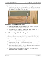
Once tightened, test the Pedal for smooth movement. If it seems
to bind, back the Nylock off slightly, until freedom of movement is
achieved.
Installation of the J-bolt for lower and upper positions
1)
Remove the Nylock and first washer from the J-Bolt and finger
tighten the remaining Hex Nut fully to the end of the thread of the
Eye Bolt.
2)
Insert the Bolt from the inside of the loom, through the existing
hole (previously used by either Tension Arm) located in the Rear
Vertical Beam of the Side Frame, above the Brake Drum.
3)
Secure the J-Bolt (with nut) to the Side Frame by replacing the
Washer and Nylock on the outside of the loom and tighten in place.
Completing the tie-up
Note:
The tie-up for the locking brake is completed in the same way whether you
are using the upper or lower position. Make sure you are using the correct
cable for the position.
1)
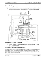
Route the Cable for your Lower Position Locking Brake from the
Pedal, upwards inside of the loom, over and around the rear of the
Brake Drum.
Содержание A Series
Страница 2: ......
Страница 17: ...A Series Dobby Loom Assembly Manual Introductory Information the Loom Page 9 Figure 1 Full Loom Left Side ...
Страница 18: ...Introductory Information A Series Dobby Loom Assembly Manual Page 10 the Loom Figure 2 Full Loom Right Side ...
Страница 19: ...A Series Dobby Loom Assembly Manual Frame Assembly Frame Assembly Page 11 FRAME ASSEMBLY FRAME ASSEMBLY ...
Страница 66: ......
Страница 100: ......
Страница 126: ......
Страница 136: ......
Страница 173: ...A Series Dobby Loom Assembly Manual The Fine Print The Fine Print Page 165 THE FINE PRINT THE FINE PRINT ...
Страница 176: ...The Fine Print A Series Dobby Loom Assembly Manual Page 168 Notice to Users in the European Union ...

