background image


1. Getting Started 


The 

Titan 9000


Series 

is a modular card based multiviewer. Each card can receive up to 4 input signals 

and up to 4 cards can be installed in the 1RU chassis. Users can monitor 4 HDMI/DVI/VGA/YPbPr 
sources via HD 1080p output. 


The Titan 9000 allows for fully free-scaling windows. A high degree of flexibility is achieved through 
internal cascading. This flexibility allows all 4 cards (16 signals) to easily be displayed on one monitor, 
and/or be duplicated to other monitors. The Titan 9000 is also extremely scalable; users can easily 
expand the system by cascading up to 10 chassis which allows for the monitoring of up to 160 sources 
on one or multiple screens. 


This chapter introduces the features and specifications as well as external components of Titan 9000. 


1.1 Package Contents 

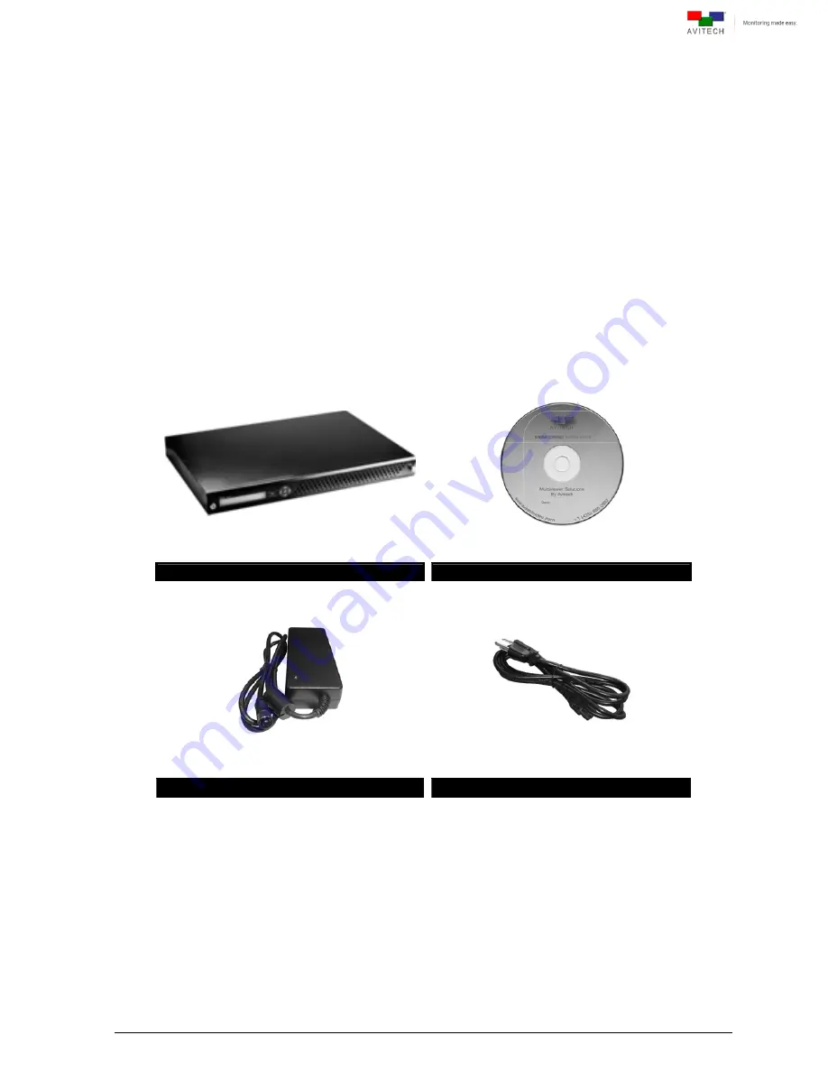
After unpacking the shipping carton, the following items can be found: 


Avitech Titan 9000


series 

Utility Disc (software and user manual) 


24 V DC Power Adapter 

Standard Power Cord (USA customer only)

Содержание Titan 9000 series

Страница 1: ...User Manual Titan 9000 Multiviewing experience taken to the next level Revision 1 0 0 May 2014 ...

Страница 2: ...are trademarks or registered trademarks of their respective companies COPYRIGHT The information in this manual is subject to change without prior notice No part of this document may be reproduced or transmitted in any form or by any means electronic or mechanical for any purpose without the express written permission of Avitech International Corporation Avitech International Corporation may have p...

Страница 3: ...usly Installed Card 17 3 Cascading 18 3 1 Internal Cascading 18 3 1 1 Example 1 Cascade 2 cards and duplicate display 18 3 1 2 Example 2 Cascade 2 cards and independent quads 20 3 1 3 Example 3 Cascade 3 cards and independent quad 22 3 1 4 Example 4 Cascade all 4 cards 23 3 2 External Cascading 25 3 2 1 Example 1 Take HDMI output of any card to the next chassis cascade input 27 3 2 2 Example 2 Ass...

Страница 4: ...110 A 1 Welcome Screen 110 A 2 Navigating the Main Menu 112 A 3 Navigating the System Parameters Menu 117 Appendix B Setting Up 1 2 2 2 Wall Display 119 B 1 Physical Connection and Bezel Gap Adjustment 119 B 2 Software Configuration 126 Appendix C Setting Up Audio 129 Sample illustration 1 137 Sample illustration 2 138 Sample illustration 3 139 Appendix D Setting Up the Alarm Sound 141 D 1 Alarm S...

Страница 5: ...ice 154 G 1 Using the Pacific GPIO Box as GPI Interface 154 G 2 Sony Production Switcher 156 Appendix H ScreenCropT Utility 158 H 1 ScreenCropT Utility Control Panel 158 H 2 Using the ScreenCropT Utility Together With the Synergy Freeware 160 H 3 Cropping Feature 163 H 4 Cropped Instances Switching 165 H 5 Pan Anywhere 166 ...

Страница 6: ...y Period Avitech makes its best offer to repair a product that is outside the warranty period provided the product has not reached its end of life EOL The minimum charge for such repair excluding shipping and handling is 200 US dollars AVITECH INTERNATIONAL CORPORATION 15377 NE 90th Street Redmond WA 98052 USA TOLL FREE 1 877 AVITECH PHONE 1 425 885 3863 FAX 1 425 885 4726 info avitechvideo com ht...

Страница 7: ...cards 16 signals to easily be displayed on one monitor and or be duplicated to other monitors The Titan 9000 is also extremely scalable users can easily expand the system by cascading up to 10 chassis which allows for the monitoring of up to 160 sources on one or multiple screens This chapter introduces the features and specifications as well as external components of Titan 9000 1 1 Package Conten...

Страница 8: ...DVI to HDMI Adapter optional D Proprietary RJ 45 to RS 232 DB9 FM Cable optional see note below Table 1 1 Package Contents Due to space limitation the serial connector is replaced with a RJ 45 connector A proprietary RJ 45 to RS 232 DB9 FM cable is needed for serial function The pin definition is shown next Figure 1 1 RJ 45 to RS 232 DB9 FM Cable Pin Definition ...

Страница 9: ...s ordered refer to the Rack Mount Assembly Reference Guide for details Rack Tray Ear left and right pc Ear A 2 pcs Ear B 2 pcs Used on 700 750 800mm rack depth 27 56 29 53 31 49 inch Tray Screw 3 4mm 4 pcs D Screw 3 7mm 6 pcs Screw 3 5mm 12 pcs D Screw 3 6mm 2 pcs ...

Страница 10: ...Supports TSL through serial interface RS 232 or Ethernet UDP 9 Supports General Purpose Input Output through Ethernet 9 Supports Avitech ASCII Protocol AAP via Ethernet connection Robust Design 9 Passed Extensive Vibration Test MIL STD 810G vibration test method 514 6 for US truck under random vibration while in operation 9 Dual power supply with DC input one main and one redundant interchangeable...

Страница 11: ... 2kHz 96kHz 176 4kHz or 192kHz sample rate 2 Analog 1 8 inch stereo headphone jack for audio monitoring 3 Audio loss audio high audio low phase detection 1 3 Specifications Titan 9000 2H2V Input HDMI HDMI type A Automatic sensing the following input signals are supported 640 350 85Hz 640 400 85Hz 640 480 60Hz 72Hz 75Hz 85Hz 720 400 85Hz 480p 59Hz 480i 59Hz 576p 50Hz 576i 50Hz 800 600 56Hz 60Hz 72H...

Страница 12: ...z 1280 800 60Hz 1280 960 60Hz 85Hz 1280 1024 60Hz 75Hz 85Hz 1360 768 60Hz 1366 768 60Hz 1400 1050 60Hz reduced blanking 60Hz 75Hz 1440 900 60Hz 1440 1050 60Hz 1600 1200 60Hz 1680 1050 60Hz 1920 1080i 50Hz 60Hz 1920 1080p 50Hz 60Hz 1920 1200 60Hz reduced blanking Transmission of audio signal is included when passing through the DVI port using the DVI to HDMI adapter VGA YPbPr through adapter Automa...

Страница 13: ...0Hz 75Hz 1680 1050 50Hz 60Hz 75Hz 1760 1100 60Hz 1920 1035 60 30Hz 1920 1080 50Hz 60Hz 60 30Hz 1920 1200 50Hz 60Hz Audio signal transmission is not included when using DVI to VGA adapter Output HDMI and DVI through HDMI to DVI adapter Normal VESA output timing 8 bit 10 bit HDMI color depth user configurable 1920 1200 WUXGA 50Hz 60Hz 1920 1080 HD 1080 50Hz 60Hz 1680 1050 WSXGA 50Hz 60Hz 75Hz 1600 1...

Страница 14: ...d blanking 60Hz 75Hz 1440 900 60Hz 1440 1050 60Hz 1600 1200 60Hz 1680 1050 60Hz 1920 1080i 50Hz 60Hz 1920 1080p 50Hz 60Hz 1920 1200 60Hz reduced blanking DVI I DVI I connector Automatic sensing the following input signals are supported 640 350 85Hz 640 400 85Hz 640 480 60Hz 72Hz 75Hz 85Hz 720 400 85Hz 480p 59Hz 480i 59Hz 576p 50Hz 576i 50Hz 800 600 56Hz 60Hz 72Hz 75Hz 85Hz 848 480 60Hz 1024 768 60...

Страница 15: ...able 1 4 Titan 9000 4H Card Specifications Only 720p and 1080p 50Hz 60Hz output resolution is available when cascading Titan 9000 HOB Input Automatic sensing from internal cascade the following input signals are supported 1280 720 50Hz 60Hz 1920 1080 50Hz 60Hz Output HDBaseT RJ45 connector For direct pairing between Titan 9000 HOB and Pacific X HDUR sold separately can be extended up to 100m 328ft...

Страница 16: ...put encoding of SMPTE Time Code data in an audio signal Electrical Single End Impedance 30k ohms Sensitivity 500 mV pk pk 5V maximum Audio Headphone jack Analog Audio audio out port Stereo Power Power consumption is 110 Watt maximum Power Supply 24 V DC 120 Watt adapter Dimensions Weight Dimensions 439 310 44 4 mm 17 3 12 2 1 8 inch Weight 4 2 kg 9 3 lb Environment Safety Temperature Operating 0 C...

Страница 17: ...3G Plus 1 is in cascade mode the output resolution can only support 720p 1080p at 50Hz 60Hz 2 In complying with the HDCP license there is no SDI conversion with HDCP video Table 1 7 Rainier 3G Plus 1 Card Specifications 1 4 Connections to the Titan 9000 Figure 1 2 Titan 9000 Front Components Front Panel Release Knob Turn the knob counter clockwise to loosen and clockwise to secure the front panel ...

Страница 18: ... to the monitor s HDMI signal cable Table 1 9 Titan 9000 2H2V Card Component Description Figure 1 4 Titan 9000 4H Card Components Rear Panel HDMI IN HDMI connector for HDMI input source HDMI OUT Connect to the monitor s HDMI signal cable Table 1 10 Titan 9000 4H Card Component Description Figure 1 5 Titan 9000 HOB Card Components Rear Panel HDBaseT RJ 45 For Titan 9000 HOB card and Pacific X HDUR ...

Страница 19: ...s not available for connecting to a computer for configuration and control Phoenix Q utility Likewise it cannot be used for entering the Avitech ASCII Protocol AAP X command interface Ethernet IP For setup through Avitech Phoenix Q utility network connection For entering the Avitech ASCII Protocol AAP X command interface For connecting to TSL port of the TSL controller for TSL interface Headset 1 ...

Страница 20: ...ecting 2 power adapters for redundant power supply make sure to maintain a distance of at least 10 cm away from each other Table 1 13 Titan 9000 Chassis Component Description Figure 1 6 Rainier 3G Plus 1 Card Components Rear Panel 1 card SDI CVBS IN BNC connector for SDI 3G HD SD CVBS NTSC PAL video sources HDMI OUT Connect to the monitor s HDMI signal cable SDI OUT BNC connector supports SDI 1080...

Страница 21: ...ower strip to the Titan 9000 before making any changes to the hardware configuration 2 1 Installing New Card on Blank Slot The Titan 9000 chassis accept any of the following cards 9 Titan 9000 2H2V card 9 Titan 9000 4H card 9 Titan 9000 HOB card 9 Rainier 3G Plus 1 card Step 1 Remove the two screws securing the back plate Figure 2 1 Remove the 2 Back Plate Screws Step 2 Remove the back plate Figur...

Страница 22: ...gn both sides of the card to the rails and slide all the way into the chassis Figure 2 4 Align the Card to the Rail on Both Sides Step 5 Secure the screws on both sides to fix the card to the chassis Figure 2 5 Secure the Screws on Both Sides Step 6 Remove the left and right puller screws on both sides of the newly installed card and re attach to the control board of the chassis Figure 2 6 Remove ...

Страница 23: ...ller screws and screw it to both sides of the card to be removed Step 3 Remove the left and right screws securing the card to be removed from the chassis Figure 2 8 Remove the Left and Right Screws Step 4 Grasp both left and right puller screws and pull the card to be removed away from the chassis Figure 2 9 Pull the Left and Right Puller Screws Step 5 Remove left and right puller screws on just r...

Страница 24: ...ore up to 10 Titan 9000 chassis to increase windows on one screen up to 160 achieved by cascading 10 Titan 9000 with 4 windows from each of the 4 cards Multiple card versions allow mix of HDMI DVI and VGA signals on one display The following illustrations would require a working knowledge of Phoenix Q software For an in depth understanding of Phoenix Q turn to the succeeding chapters for more info...

Страница 25: ...ither left or right illustration below and then click OK Figure 3 3 Phoenix Q Software Set Subgroup Configuration There is no need to make any adjustments in the HDMI OUT item in Properties panel as the software smartly does it Figure 3 4 Phoenix Q Software Properties HDMI OUT Display Source ...

Страница 26: ... cards and independent quads Step 1 Make sure that 2 card ID belong to the same group while the other 2 card ID are each assigned a group by itself Verify this as shown on the Group View tree found on the left panel of the Phoenix Q software To change the group setup go to SystemÆConfiguration Figure 3 6 Phoenix Q Software Group View Panel ...

Страница 27: ... the HDMI OUT item in Properties panel as the software smartly does it Figure 3 7 Phoenix Q Software Properties HDMI OUT Display Source The following figure illustrates the above setup Figure 3 8 Cascade 2 Cards and 2 Independent Quad Illustration ...

Страница 28: ...f Verify this as shown on the Group View tree found on the left panel of the Phoenix Q software To change the group setup go to SystemÆConfiguration Figure 3 9 Phoenix Q Software Group View Panel There is no need of any adjustments in the HDMI OUT item in Properties panel as the software smartly does it Figure 3 10 Phoenix Q Software Properties HDMI OUT Display Source ...

Страница 29: ...Illustration 3 1 4 Example 4 Cascade all 4 cards Step 1 Make sure that all 4 card ID belong to the same group Verify this as shown on the Group View tree found on the left panel of the Phoenix Q software To change the group setup go to SystemÆConfiguration Figure 3 12 Phoenix Q Software Group View Panel ...

Страница 30: ...ments in the HDMI OUT item in Properties panel as the software smartly does it Figure 3 13 Phoenix Q Software Properties HDMI OUT Display Source The following figure illustrates the above setup Figure 3 14 Cascade 4 Cards Illustration ...

Страница 31: ...CADE IN HDMI port of the next Titan 9000 s control card in the chain Step 3 Cascading through RJ 45 RS 485 is used to loop communication from one Titan 9000 to the next The data stream carries control and configuration information Connect one end of RS 485 cascading cable to the RS 485 OUT of the first Titan 9000 and the other end to RS 485 IN of the next Titan 9000 in the chain Step 4 Connect one...

Страница 32: ...26 The following illustration shows a typical setup of cascaded Titan 9000 Figure 3 15 Cascaded Titan 9000 Illustration ...

Страница 33: ...me group Likewise assigning card s to another group allows display of second group s window on a second monitor Card ID 1 output to the next chassis cascade input Figure 3 16 Phoenix Q Properties HDMI OUT Display Source Setting 9 Upon selecting Card 1 for HDMI 1 then only the 4 windows of card ID 1 16 windows of chassis ID 2 will be displayed Figure 3 17 HDMI Output of Card ID 1 to the Next Chassi...

Страница 34: ...be displayed Figure 3 18 HDMI Output of Card ID 1 to the Next Chassis Cascade Input Illustration 2 9 Upon selecting Card 3 for HDMI 1 then only the 12 windows of card ID 1 and 2 and 3 16 windows of chassis ID 2 will be displayed Figure 3 19 HDMI Output of Card ID 1 to the Next Chassis Cascade Input Illustration 3 ...

Страница 35: ...s of card ID 1 16 windows of chassis ID 2 will be displayed 9 Upon selecting Card 2 for HDMI 2 then only the 8 windows of card ID 1 and 2 16 windows of chassis ID 2 will be displayed 9 Upon selecting Card 3 for HDMI 2 then only the 12 windows of card ID 1 and 2 and 3 16 windows of chassis ID 2 will be displayed 9 Upon selecting Card 4 for HDMI 2 then all 16 windows of card ID 1 and 2 and 3 and 4 1...

Страница 36: ... 8 windows of card ID 1 and 2 16 windows of chassis ID 2 will be displayed 9 Upon selecting Card 3 for HDMI 3 then only the 12 windows of card ID 1 and 2 and 3 16 windows of chassis ID 2 will be displayed 9 Upon selecting Card 4 for HDMI 3 then all 16 windows of card ID 1 and 2 and 3 and 4 16 windows of chassis ID 2 will be displayed Figure 3 22 HDMI Output of Card ID 3 to the Next Chassis Cascade...

Страница 37: ... 8 windows of card ID 1 and 2 16 windows of chassis ID 2 will be displayed 9 Upon selecting Card 3 for HDMI 4 then only the 12 windows of card ID 1 and 2 and 3 16 windows of chassis ID 2 will be displayed 9 Upon selecting Card 4 for HDMI 4 then all 16 windows of card ID 1 and 2 and 3 and 4 16 windows of chassis ID 2 will be displayed Figure 3 23 HDMI Output of Card ID 4 to the Next Chassis Cascade...

Страница 38: ...g card s to another group allows display of second group s window on a second monitor For the purpose of this illustration let us focus our Phoenix Q setting for chassis ID 2 9 To assign the input source signals of card ID 1 only from chassis ID 2 to be displayed select Card 1 for HDMI 4 Only the 4 windows of chassis ID 2 card ID 1 16 windows of chassis ID 1 16 windows of chassis ID 3 will be disp...

Страница 39: ...only from chassis ID 2 to be displayed select Card 2 for HDMI 4 Only the 8 windows of chassis ID 2 card ID 1 and 2 16 windows of chassis ID 1 16 windows of chassis ID 3 will be displayed Figure 3 25 Assign Any or Multi cards to the Cascade Output Illustration 2 ...

Страница 40: ...y from chassis ID 2 to be displayed select Card 3 for HDMI 4 Only the 12 windows of chassis ID 2 card ID 1 and 2 and 3 16 windows of chassis ID 1 16 windows of chassis ID 3 will be displayed Figure 3 26 Assign Any or Multi cards to the Cascade Output Illustration 3 ...

Страница 41: ... chassis ID 2 to be displayed select Card 4 for HDMI 4 All 16 windows of chassis ID 2 card ID 1 and 2 and 3 and 4 16 windows of chassis ID 1 16 windows of chassis ID 3 will be displayed Figure 3 27 Assign Any or Multi cards to the Cascade Output Illustration 4 ...

Страница 42: ...rce signals of all 4 cards from chassis ID 2 select Cascade In for HDMI 4 Only the 16 windows of chassis ID 1 16 windows of chassis ID 3 will be displayed Figure 3 28 Assign Any or Multi cards to the Cascade Output Illustration 5 ...

Страница 43: ...nnect your Titan 9000 to the controlling computer through an Ethernet cable IP address Before connecting the computer to the Titan 9000 the computer will need to be changed to a static IP and its subnet mask must be set to a similar range as the Titan 9000 e g 192 168 0 5 factory default setting Or the IP address of the Titan 9000 Master chassis can be changed to a similar range as the controlling...

Страница 44: ...tarting Up the Phoenix Q Software Step 1 Run the Phoenix Q software by double clicking Phoenix Q exe Step 2 Make sure you have set the correct IP address see Appendix E for details Step 3 Select the only type of connection allowed by clicking IP Port checkbox Then click Connect Figure 4 3 Phoenix Q Software Select the Ethernet Connection Method ...

Страница 45: ...different rotary ID setting selected e g 1 2 3 on their rear chassis The Group View window will list the card s found and will initially be listed under Idle Group 1 If you have 2 or more chassis cascaded they should also be detected 2 Make sure that the slave chassis baud rate and resolution is the same as the master chassis Figure 4 5 Phoenix Q Software Idle Group ...

Страница 46: ...40 Step 4 Click SystemÆConfiguration Figure 4 6 Phoenix Q Software Click System Æ Configuration The Group Setup window will appear Figure 4 7 Phoenix Q Software Group Setup ...

Страница 47: ...on the right panel e g Group 001 Figure 4 8 Phoenix Q Software Assign Group to Idle Device Or click the One Device Per Group button to assign a card to each group or click All Devices in Group 1 to assign all cards to belong to Group 1 The Titan 9000 HOB card must be assigned a group by itself ...

Страница 48: ...tup window Phoenix Q will save the configuration file System agi to the device s flash memory Figure 4 10 Phoenix Q Software Update Configuration Progress After group setup has been completed and every time IP address of master chassis has been changed see Appendix E perform the simple step of entering Group Setup window and then clicking OK to exit there is no need to re assign grouping This will...

Страница 49: ...fies audio O utput that is H DMI OUT Figure 4 11 Phoenix Q Software Chassis and Card ID Place the mouse pointer over a specific card ID to show various information such as Master IP Chassis ID Card ID Audio Output reference guide Figure 4 12 Phoenix Q Software Device Information and Reference 4 4 Obtaining the UMD Under Monitor Display Data from Router Step 1 Click SystemÆDisconnect Figure 4 13 Ph...

Страница 50: ...oenix Q software Figure 4 14 Phoenix Q Software Confirm Disconnection The progress of disconnection will appear on screen Figure 4 15 Phoenix Q Software Disconnection Progress Step 2 Click SystemÆOptions Figure 4 16 Phoenix Q Software Click System Æ Options ...

Страница 51: ...Q Software Enable External Device Step 4 Make sure that the IP Address corresponds to the IP address of the computer running the tpcGW utility If not click the IP Address button and when the IP Address screen appears enter the correct value Then click OK to exit Figure 4 18 Phoenix Q Software Enter Correct IP Address ...

Страница 52: ...ure 4 19 Phoenix Q Software Enter Correct Port Number Make sure the value appearing for both IP Address and Port Number are similar to the value entered in the tpcGW utility they must be to be able to successfully connect to the router Step 6 To allow the Phoenix Q software to connect to the router use the tpcGW utility refer to the tpcGW Utility Quick Reference Guide for details ...

Страница 53: ...odel will depend on the monitor s resolution as well as the smallest window size limitation Figure 4 20 Phoenix Q Software Group Layout Upon selecting Custom Layout specify the Window Ratio Normal 4 3 16 9 If Normal is selected then you can set the Horizontal and Vertical number of windows 2 to 8 as possible grid positions on the monitor If 4 3 or 16 9 is selected then you can only set the Horizon...

Страница 54: ...ter of a window and drop to a new position It will be updated on the monitor Or upon selecting a window use the left right up down arrow buttons on your keyboard 4 5 3 Full Screen Mode Swap Window Contents Full Screen Mode Double click a window to enter full screen mode Double click again to return from full screen mode Swap Window Move cursor to the bottom left hand corner of a window until a let...

Страница 55: ...ing Step 2 Click to select the particular Group card ID on the left column Click the destination Visual Studio group on the right column Click the right arrow button Select other Group card ID to belong to a Visual Studio group Multiple Group card ID can be assigned to the same Visual Studio group Finally click OK to exit the Visual Studio Setup window To remove a particular Group from the previou...

Страница 56: ...earing on the Visual Studio tab may be stacked on top of each other Assign the Layout to display the other card ID Quick Information Positioning the cursor on top of a window will provide a quick information of the window As well as the prompt Double click Æ window label to allow you to quickly bring up the particular group s layout view in the main window of Phoenix Q Figure 4 27 Visual Studio Wi...

Страница 57: ...l Studio Set the Border and Label Color Auto Arrange Allow the system to automatically arrange the layout of the windows appearing in the Visual Studio tab Figure 4 30 Visual Studio Auto Arrange 4 5 5 Available Windows Image windows that are disabled turned off reside in a tab called Available Windows Figure 4 31 Properties Tab Turn Off Image Window ...

Страница 58: ...2 Properties Tab Turn On Image Window Method 2 Drag the window to be enabled to the Group xxx tab Action drag window to an empty location will allow the selected window to appear in the previously empty space Action drag window on top of another window will cause the former occupant window to be disabled turned off and moved to Available Windows tab Figure 4 33 Properties Tab Turn On Image Window ...

Страница 59: ...indow CardÆImage 1 2 3 4 3 all the cards belonging to the same Group 4 to the entire System Figure 4 35 Phoenix Q Software Right click Item to Quickly Apply Settings to Card Group System The properties of a window can be copied to another window on the same card as well as between cascaded chassis Right click a window select Copy to and click the following to quickly apply the settings to 1 all th...

Страница 60: ...d vertical markers 9 Meter 1 on off switch 2 layout and alarm trigger 3 group 4 width 5 vertical coordinates and 6 VU PPM switch 9 Image border 1 on off switch 2 width and 3 color 9 Video border 1 on off switch 2 width and 3 color You can also close a particular window by clicking Close The Window would appear as an icon on the Available Windows pane To activate the window again just drag the wind...

Страница 61: ...lign Right button aligns the right edges of the windows with each other To align a set of windows horizontally vertically Step 1 Select the windows by clicking the first window with the left mouse button and the succeeding windows using the keyboard s Ctrl key left mouse button Other computer applications that are currently running which use the same Ctrl key left mouse button hot key may disable ...

Страница 62: ...ight size of the last window selected 9 copy width 9 copy height To prevent distortion on the window s image for interlaced input signal make sure the height of the image excluding label and border IS NOT smaller than one half of the vertical active region of input source e g if resolution is set at 1080i 50Hz then the image s height must not be less than 540 pixels 9 copy size To undo window s si...

Страница 63: ... To indicate whether you want to eliminate the vertical horizontal spacing between the windows click one of the following buttons The position of the last window selected do not change but the other window s changes position to remove any vertical horizontal spacing in between 9 horizontal 9 vertical 1 Remove Horizontal Spacing button is disabled grayed out if any of 2 consecutive windows selected...

Страница 64: ...ta Figure 4 40 Phoenix Q Software Save Log Window Information You can also refer to your computer s hard drive C Avitech Backup Backup_date_time Log folder for various system log messages text file Figure 4 41 Phoenix Q Software Location of Auto save Log File ...

Страница 65: ...sets you create are stored in the Titan 9000 flash memory not on your computer After creating a preset you will need to save to flash in order to write all the presets into the internal flash memory of the Titan 9000 To save a preset perform the following steps Save Preset is not available for Titan 9000 HOB Step 1 Configure the window layout to how you want it to be displayed Step 2 Click Save Pr...

Страница 66: ... right clicking the filename and clicking Delete Figure 5 3 Phoenix Q Software Delete File in Save Window To delete all the files appearing on the window right click anywhere inside the window except on the filename itself and click Delete All When the confirmation window appears click OK to proceed Figure 5 4 Phoenix Q Software Delete All Preset Files Confirmation Step 4 After you are done creati...

Страница 67: ...delete all files appearing on the window right click anywhere inside the window except the filename itself and click Delete All When the confirmation window appears click OK to proceed Step 6 Click Exit to close the Phoenix Q software and all the changes would be automatically saved to the configuration file System agi in the device s flash memory 5 2 Edit Menu Figure 5 6 Phoenix Q Software Edit M...

Страница 68: ...On the next screen click Font settings Step 4 On the next screen click to unselect the Hide fonts based on language settings checkbox Then click OK to exit Step 5 On the Phoenix Q software click to select Arial as the default Font and click OK 5 3 View Menu Figure 5 8 Phoenix Q Software View Menu View Menu Toolbars and Docking Windows Enable with checkmark or disable the display of any of the tool...

Страница 69: ...ell as Customize display Figure 5 9 Phoenix Q Software Toolbars and Docking Windows Menu Customize Click Customize to design the look of the menus and commands appearing on the Phoenix Q software Click the particular folder Commands Toolbars Menu and Options and then make the necessary changes Click Close when finished to exit Figure 5 10 Phoenix Q Software Customize the Toolbars Window ...

Страница 70: ...ct the overall design and theme of the Phoenix Q software Click on the themes title to view the theme Note The dot in front of Visual Studio NET 2005 signifies that it is the currently selected theme Figure 5 11 Phoenix Q Software Application Look Menu ...

Страница 71: ...ick Communication to select the IP Port Ethernet mode of connection between the computer and Titan 9000 Note This item is not available when the computer is connected to the Titan 9000 Simulation Note For factory testing only this item is not available Restore To restore a preset follow the steps outlined in figures 5 13 to 5 16 Setup Speaker ID Use Setup Speaker ID to set up which speakers monito...

Страница 72: ...Click System Æ Restore Æ Configuration and Files Step 4 The Date window shows various folders with the date automatically generated when preset s were previously saved The Preview Configuration window shows the setup of the just selected folder The Present Configuration window shows the present setup of Titan 9000 Figure 5 14 Phoenix Q Software Restore Window Step 5 Click to select a restore point...

Страница 73: ...2013_03_05_14_15_10 folder in the Date window then restore is not allowed by the system and the Restore button remains grayed out Step 6 Click Restore The progress of restoration will be shown Figure 5 15 Phoenix Q Software Restore Progress Step 7 Reboot the Titan 9000 to complete the Restore process Figure 5 16 Phoenix Q Software Reboot Device ...

Страница 74: ...rd ID to output to which chassis ID headset connector Make sure to first assign 2 or more chassis ID cards to the same group Figure 5 17 Phoenix Q Software Click System Æ Setup Speaker ID Figure 5 18 Phoenix Q Software Card Speaker ID This item is only available when the computer is connected to the Titan 9000 ...

Страница 75: ...when the computer is connected to the Titan 9000 3 Refer to Appendix D for complete details on using the Import Export Æ Alarm Sound function Export the label to be edited externally The most convenient way is to export the file label as 9 ANSI up to 30 characters can contain the English characters A Z a z 0 9 or 9 BMP Label Unicode up to 15 characters useful for displaying text other than the Eng...

Страница 76: ...two types of labels A for ANSI B for BMP Label Change the label type as desired by typing A or B after the dash highlighted as shown below Figure 5 21 Phoenix Q Software Change Label Type Step 3 Then edit the text in the file highlighted as shown below When you are done editing the label save the txt file and import it The on screen labels will be updated Figure 5 22 Phoenix Q Software Change Labe...

Страница 77: ...neralÆBackup Path The default backup path C Avitech Backup contains the system configuration preset files system log data and firmware version information To change the backup path type the desired path in the Value column available when Phoenix Q is not connected to chassis Figure 5 24 Options System Æ General Æ Backup Path ...

Страница 78: ...older Then click OK to exit Figure 5 25 Phoenix Q Software Select Folder Window 9 GeneralÆDuring Program Startup Click the drop down button click the cell s rightmost portion to select Open Communication window that allows the Phoenix Q program to automatically open the Communication window upon startup Figure 5 26 Options System Æ General Æ During Program Startup ...

Страница 79: ...s System Æ General Æ New Device Detected To prevent error when detecting the new device it is highly recommended the new device to return to its default setting before connecting it to the present setup 9 GeneralÆLayout Display Click the drop down button click the cell s rightmost portion to select Center or Upper left corner that allows the preview window to be displayed in the center or upper le...

Страница 80: ...eral Æ Display Device ID Group View 9 GeneralÆVideo Black Threshold Unit Set the level in IRE or mV below which the signal will be considered to be black Click the drop down button click the Video Black Threshold Unit cell s rightmost portion to select IRE or mV IRE is a unit used in the measurement of composite video signals Its name is derived from the initials of the Institute of Radio Engineer...

Страница 81: ... Audio Output Follow SDI SPDIF Audio Output is enabled set On Click the drop down button click the HDMI Audio Output Follow SDI SPDIF Audio Output cell s rightmost portion to select On Figure 5 31 Options System Æ General Æ HDMI Audio Output Follow SDI SPDIF Audio Output Upon selecting On the following reminder appears Figure 5 32 Reminder Upon Enabling HDMI Audio Output Follow SDI SPDIF Audio Out...

Страница 82: ...n mode Figure 5 33 Options System Æ General Æ Audio Output From Full Screen Window Not applicable when Titan 9000 is cascaded with Rainier 3G 9 GeneralÆSpecial Audio Link Between Cascaded Device To allow the audio signal to pass through between cascaded Titan 9000 and Rainier 3G both device must belong to the same group make sure Special Audio Link Between Cascaded Device is enabled set On Click t...

Страница 83: ... 30 characters Figure 5 35 Options System Æ General Æ Visual Studio Name 9 GeneralÆDisplay NameÆType To change the group s displayed name select Custom Click the drop down button click the Type cell s rightmost portion to select Custom Figure 5 36 Options System Æ General Æ Type ...

Страница 84: ...em Æ General Æ Custom Name 9 Play Special Layout No Video Make sure that Play Special Layout when No Video occurs is Enabled set On Click the drop down button click the Display Type cell s rightmost portion to select Quad or Full screen Figure 5 38 Options System Æ Play Special Layout No Video Æ Display Type ...

Страница 85: ...ses video signal Allows the window layout to revert back to where it was before signal loss occurred Click the drop down button click the Auto Restore cell s rightmost portion to select On When Auto Restore is disabled set Off then right click the window and select Close to allow the window layout to revert back to where it was before signal loss occurred Sample scenario 2 window 2 has regained vi...

Страница 86: ...e is set On Figure 5 40 Options External Device Æ Communication Æ Device Enable 9 External DeviceÆIP Address Make sure that the IP Address corresponds to the IP address of the computer running the tpcGW utility If not click the IP Address button and when the IP Address screen appears enter the correct value Then click OK to exit Figure 5 41 Options External Device Æ Communication Æ IP Address ...

Страница 87: ...umber must be similar to the value entered in the tpcGW utility to be able to successfully connect to the router 5 5 Help Menu Figure 5 43 Phoenix Q Software Help Menu Help Menu Firmware Version Click to export as a txt file Upgrade Firmware Click Upgrade Firmware to bring the device s firmware up to date see Firmware Upgrade Reference Guide for details About Click About to see a pop up window whi...

Страница 88: ...5 Phoenix Q Software Save Firmware Version Information Upgrade Firmware Click Upgrade Firmware to bring the device s firmware up to date see Firmware Upgrade Reference Guide for Titan 9000 for details Click System Æ Disconnect first before firmware upgrade About Click About to see a pop up box showing the Phoenix Q software information Figure 5 46 Phoenix Q Software Version Information ...

Страница 89: ...tep 2 Enter the Process name specify the Time H M S then select the previously saved preset File Click OK to continue Continue adding new processes as necessary Figure 5 48 Phoenix Q Software Add Process Window Step 3 On the drop down menu you can select Auto Play Auto Play Repeat Manual or Manual Repeat Click play to start viewing the slideshow Figure 5 49 Briefing Select Type of Playback ...

Страница 90: ...to select the Card on the Group View window left panel and the Properties window right panel would list the parameters available for setup Figure 6 1 Phoenix Q Software Properties Window Some of the items appearing on the Properties window may or may not be available for your Titan 9000 ...

Страница 91: ...232 port with a TSL connection Note RS 232 port is not for connecting to a computer for configuration Phoenix Q utility Likewise it cannot be used for entering any Avitech ASCII commands When configuring connect the Master Titan 9000 to the controlling computer via an Ethernet connection and then connect the Master Titan 9000 RS 232 port to the TSL router Note To implement TSL aside from selecting...

Страница 92: ...ter is enabled Serial Port TSL V3 1 will automatically be disabled HDMI OUT Display Source HDMI 1 2 3 4 Card 1 2 3 4 Cascade In Select the display source for output to each card s HDMI OUT port You can select another card s HDMI DVI IN source as output to another card s HDMI OUT port Or use the source signal coming into the chassis CASCADE IN port as output to a card Note 1 Only 720p and 1080p 50H...

Страница 93: ...arameters Enable On Off Turn on the power alarm feature that is triggered when either one of the power from redundant power source is cut off Time Lag Always on 1 5 10 30 minutes 1 2 6 12 24 hours Set the time interval between cut off of one of redundant power source and when power alarm is shown on screen Display Time Seconds 1 to 120 Set the length of time that power alarm remains on screen Card...

Страница 94: ...for Rainier 3G Plus 1 card Audio Alarm Lock On Off Turning on audio alarm lock allows the alarm during occurrence of NO AUDIO OUT OF PHASE to remain on screen even after audio signal has resumed streaming from the input source This feature is most useful when the operator is away and wants to keep track of occurrence of no audio out of phase Note To remove NO AUDIO text on screen click Erase Alarm...

Страница 95: ... Custom tab by setting the Hue Saturation Luminance as well as the Red Green Blue values Headphone Local Enable On Off Allow audio output from headphone connected to audio output connector Source Select the source of the audio signal to be played on headphones Window 1 2 3 4 embedded audio or pass through embedded audio supports linear pulse code modulation only Channel Select the source of audio ...

Страница 96: ...ile is larger than the card s output resolution see Card ParametersÆ Resolution the system will automatically detect and prevent it from displaying as your user logo picture Position X Y Specify the location of the screen logo appearing on screen by setting the X and Y coordinates Clock Enable On Off Allow the display of clock on screen Border Enable On Off Allow the display of border on digital c...

Страница 97: ...me server Note This item is only available when you select SNTP in Source Pause On Off Allows you to pause resume the time count Note This item is only available when you select Counter in Source Count Up Down Select the counting method Up forward or Down reverse Note This item is only available when you select Counter in Source Reset Counter Allows you to reset the counter Note This item is only ...

Страница 98: ...4 5 6 7 8 Note This item is only available when you select Counter in Source Index 1 2 3 4 5 6 7 8 Change Set the preset time displayed for each input source Note This item is only available when you select Counter in Source Label Clock Display On Off Allow the display of the clock s label default label is Clock BMP Label On Off Allow the display of universal fonts for the on screen clock Text Cha...

Страница 99: ...indows Display Signal Format On Off Allow the display of window s input signal format Crop Area Size Crop Image Set the specific size of the crop zoom in image on a particular window Freely adjust the horizontal Left and Right and vertical Top and Bottom markers to set the size of the cropped image You can also click the buttons to make smaller adjustments Note 1 Any adjustments using the marker b...

Страница 100: ...indow After creating the cropped image zoomed in area you can still click the buttons to make smaller adjustments to the markers Then use the mouse drag with the symbol to pan the cropped image window zoomed in area The viewing area is only limited to the cropped image zoomed in area Freely adjusting the horizontal Left and Right and vertical Top and Bottom markers would cause a stretching shrinki...

Страница 101: ...ge for interlaced input signal make sure height of image excluding label and border IS NOT smaller than one half of vertical active region of input source e g if resolution is set at 1080i 50Hz then image s height must not be less than 540 pixels Lock Position On Off Lock or unlock the position of the window appearing on screen Label Display On Off Show the label appearing on the window Keep in mi...

Страница 102: ...ult aspect ratio will follow settings on next two items HD SDI fixed at 16 9 and SD SDI Composite 4 3 16 9 Upon selecting AFD protected area shown on screen takes priority Note This item only appears for Rainier 3G Plus 1 card Fit Image Size On Off Upon selecting On the image will fit the window size Meter Meter Enable On Off Allow the audio meter for the particular window to appear on screen ...

Страница 103: ...97 Image Layout and Alarm Trigger Change Audio meter scale ...

Страница 104: ...ch group This allows you to display the left and right VU meter of either the master or secondary channel on the left and right side of the window just as the menu depicts Adjust the Phase Out of phase slider VU one slider Sound H L sliders If there is no audio detected you will NOT see any VU meters Audio Meters Groups Along with the video signal s each input signal may contain up to sixteen chan...

Страница 105: ...allows you to select the type of PPM scale Nordic BBC EBU DIN Whereas the VU meter has fairly equal attack and release times the PPM is characterized by having a very slow fall back time taking over 1 5 seconds to fall back 20dB the specifications vary slightly for Type I and II meters The reasoning for the slow fall back was to reduce eye fatigue and make the peak indication easier to assimilate ...

Страница 106: ...slider to the right you can increase the vividness of a blue sky in an image By moving the slider to the left you can reduce the vividness of color You can create a black and white image effect by moving the slider all the way to the left so that all color in the image is removed Note This item only appears for Rainier 3G Plus 1 card Contrast 0 to 1023 Adjust the difference in tone between the dar...

Страница 107: ...tem only appears for Titan 9000 2H2V card 2 The values of H_Start plus Width must not exceed H_Total 3 The value of V_Total based on the values of V_Start plus Height must not exceed the value automatically computed by the software based on the input signal s pre determined value for V_Total Change the Gain s value if necessary This function can fix the image coloring problem intensity Select if t...

Страница 108: ...nce the criteria video detect area and threshold for video black has been detected Note This item only appears for Rainier 3G Plus 1 card Video Freeze Enable On Off Activate the video freeze alarm feature Freeze detection is done by comparing successive frames based on the parameters set on the next two items Sensitivity Level and Set Duration Once the alarm is triggered it will only be released i...

Страница 109: ...mage border to the color Red as warning Flash On Off Set the image border to Flash as warning Response Time Signal In Out 0 25 to 49 75 Set the Signal In Out alarm response time such as when inputting the signal or change of status from abnormal to normal Alarm Sound Video Enable On Off Activate playback of alarm sound when no video video black freeze is detected in a particular window Note To ena...

Страница 110: ...s item only appears for Rainier 3G Plus 1 card Position X 0 to 75 Specify the location of the Time Code appearing on screen by setting the X and Y coordinates percentage in relative position to the screen Note This item only appears for Rainier 3G Plus 1 card Position Y 0 to 98 5 Specify the location of the Time Code appearing on screen by setting the X and Y coordinates percentage in relative pos...

Страница 111: ... enabled Serial Port TSL V3 1 will automatically be disabled Cascade In Color Correction HDMI On Off Turn on off encoder signal in out stage to fix any color anomaly that may appear on color edge of signal entering the CASCADE IN HDMI port HDMI OUT Display Source HDMI 1 2 3 Card 1 2 3 Cascade In Select the display source for output to each Titan 9000 HOB card s DVI D OUT port You can select anothe...

Страница 112: ...e This item is only available when the item Output Display Mode is set Single Crop Size X Y Specify the location of the window appearing on screen by setting the X and Y coordinates Note Item only available when item Output Display Mode is set Wall Width Height Specify the cropped size of the window appearing on screen by setting the Width and Height values You can directly input the value use the...

Страница 113: ...ns Group Reset and Set to Default is available 9 Click Group Reset to refresh all cards belonging to the same group 9 Click Set to Default to return all cards belonging in the same group to its default settings 9 1920 1080 output resolution 60 Hz vertical frequency 9 Normal output timing 9 Default preset layout 8 windows per row total number of rows depending on number of cards on each chassis as ...

Страница 114: ...ng between the cards within a Titan 9000 left figure below the solid line linking the third and fourth unit signify external cascading between 2 Titan 9000 right figure below Likewise a solid line links the last internal cascaded card or last external cascaded card to the monitor Figure 6 3 Phoenix Q Software Cascade In Switch Device Cascade Series Window standalone Titan 9000 left 2 cascaded Tita...

Страница 115: ...tual physical connection of the cascaded Titan 9000 9 Click Clear Tally Status to clear up any tally that has appeared on screen 9 Import txt ÆLabel from Export txt ÆLabel to be edited externally The most convenient way is to export the file label as 9 ANSI up to 30 characters can contain the English characters A Z a z 0 9 or 9 BMP Label Unicode up to 15 characters useful for displaying text other...

Страница 116: ... A 1 LCD Panel Busy State 1 When the busy state PLEASE WAIT message is displayed on the LCD panel see sample screen above DO NOT disconnect or connect any signal cables as a fault may occur 2 Also DO NOT change any of the incoming signal s display resolutions while the Titan 9000 is in the busy state 3 LCD panel is unavailable for configuration when Phoenix Q is connected to the Titan 9000 Etherne...

Страница 117: ...111 Figure A 4 LCD Panel Menu Tree ...

Страница 118: ...ur choice of resolution to 1920 1080 50 60 Hz and 1280 720 50 60 Hz only 1 When Cascade is turned on for the particular card 2 When a particular card belongs to a group via Phoenix Q software Exit Exit the output resolution and frequency setup menu Table A 1 Output Resolution and Frequency Output Timing Standard Normal VESA select this for HDMI DVI output Exit Exit the output timing setup menu Tab...

Страница 119: ...ce windows 9 Image 1 2 3 4 Primary Group select the primary group for HDMI audio 9 Group 1 2 3 4 Secondary Group select the secondary group for HDMI audio 9 Group 1 2 3 4 Exit Exit the headphone audio setup menu Table A 4 Audio Cascade Status On enable the card s cascade feature SOURCE select the card s 1 2 3 4 cascade source 9 Card 1 2 3 4 9 Cascade In Off disable the card s cascade feature Note ...

Страница 120: ...aded the next time the Titan 9000 is turned on Note This action is similar to the automatic system parameter save when quitting the Phoenix Q program Exit Exit the preset file setup menu Table A 7 Preset File Color Correction Status On enable the color correction feature Off disable the color correction feature Exit Exit the color correction setup menu Table A 8 Color Correction Pattern Available ...

Страница 121: ... available when you select On in Signal Format Exit Exit the display AFD setup menu Table A 13 Window Display AFD 9 When the Display AFD feature is set ON and AFD is present in the input signal then the Aspect Auto Detect function later item will be automatically disabled 9 When the Display AFD feature is set ON but AFD is not present in the input signal then this function is invalid and the Aspec...

Страница 122: ...u Table A 19 Window Automatic Aspect Ratio Detection Safe Area Not available for Titan 9000 HOB card Status On display the safe area marker of window Note the default settings are 0 and 100 thus you will need to first create and save parameters using Phoenix Q before safe area will display a result Off disable the safe area marker of the window Exit Exit the safe area setup menu Table A 20 Window ...

Страница 123: ...rightness quality of the input signal 9 128 to 127 Saturation adjust the saturation quality of the input signal 9 0 to 1023 Contrast adjust the contrast quality of the input signal 9 0 to 1023 Hue adjust the hue quality of the input signal 9 1024 to 1023 Default Exit Exit the image adjustment setup menu Table A 23 Window Image Adjustment Depending on the type of video signal SATURATION and HUE may...

Страница 124: ... case you forgot the password for unlocking the LCD panel just press both and buttons simultaneously and enter Avitech default password Firmware Version Reference Show the various current firmware version for reference CB AX controller board CB FPGA field programmable gate array Cx Merge FPGA C stands for card x the card number 1 to 4 Cx OSD on screen display FPGA Cx ST 1 chip 1 Cx ST 2 chip 2 Cx ...

Страница 125: ...ical model and size of monitors when outputting a signal source simultaneously to two 1 2 wall display or two 2 2 wall display 3 It is highly recommended to input at 1920 1080 and output at 1920 1080 resolution B 1 Physical Connection and Bezel Gap Adjustment Step 1 For a 1 2 wall display configuration with 2 monitors identical model and size of monitors placed side by side on a wall connect a mon...

Страница 126: ... port third monitor to Card ID 4 DVI D OUT 1 port and fourth monitor to Card ID 4 DVI D OUT 2 port Step 2 Enable the Line test pattern to align the 2 monitor display for a 1 2 wall display configuration Or align the 4 monitor display for a 2 2 wall display configuration Step 3 For 1 2 wall display configuration only Select the 1 2 Group Layout display configuration Step 4 Perform Bezel Gap Adjustm...

Страница 127: ...20 1080 Step 3 Enter the pixel pitch mm of the monitor data obtained from monitor specification Step 4 Enter the bezel gap mm 4 sides of the monitor When this information is not included in the documentation that came with the monitor then use a ruler to measure Step 5 Click the Suggested Value button Notice that the Left Top Right Bottom windows under the Suggest column will be updated Step 6 For...

Страница 128: ... margins for monitor top left position Click the Apply to HOB output button Step 7 For setting the top right monitor of 2 2 wall display Select the output port for the top right monitor from the HOB Device drop down window On the Clear column click the radio button for Right and Top because we do not need to specify both margins for monitor top right position Click the Apply to HOB output button S...

Страница 129: ...Right and Bottom because we do not need to specify both margins for monitor right bottom position Click the Apply to HOB output button Step 10 Click Exit button The figure below on the left shows the new values for Window 1 and 2 of Card ID 3 while the figure on the right shows the new values for Window 1 and 2 of Card ID 4 Is the image aligned to your satisfaction If not use the slider 2 pixel in...

Страница 130: ...ication Step 4 Enter the bezel gap mm 4 sides of the monitor When this information is not included in the documentation that came with the monitor then use a ruler to measure Step 5 Click the Suggested Value button Notice that the Left Top Right Bottom windows under the Suggest column will be updated Step 6 For setting the left monitor of 1 2 wall display Select the output port for the left monito...

Страница 131: ...put port for the right monitor from the HOB Device drop down window On Clear column click radio button for Right and Top and Bottom Click the Apply to HOB output button Step 8 Click Exit button Figure below shows new values for Window 1 and 2 of single HOB Card Is the image aligned to your satisfaction If not then use the slider 2 pixel increments to make your final adjustments ...

Страница 132: ... HDBaseT port then connect a monitor to the HDMI OUT DVI OUT port Connect an Ethernet cable from Card ID 3 HDBaseT 2 port to the second Pacific X HDUR HDBaseT port then connect a monitor to the HDMI OUT DVI OUT port Connect an Ethernet cable from Card ID 4 HDBaseT 1 port to the third Pacific X HDUR HDBaseT port then connect a monitor to the HDMI OUT DVI OUT port Connect an Ethernet cable from Card...

Страница 133: ...signal source for the Titan 9000 HOB card under Card Parameters The following steps 2 to 5 need be performed for 1 2 wall display configuration only Step 2 Enable the Special Control Mode HOB 1 2 option to allow the proportional display of 1 2 wall display windows in the Visual Studio tab Step 3 Select the 4 2 Group Layout display configuration Step 4 Out of the 12 source windows close 7 windows s...

Страница 134: ...128 Step 5 Manually re size and rearrange the 5 windows to obtain the below example display ...

Страница 135: ...rd will output to a particular chassis headset connector Make sure that 2 or more cascaded chassis cards belong to the same group Step 2 To allow audio monitoring via the headphone connected to the headset port of the chassis make sure to make the correct settings for the items under Headphone Parameters Mute Off Sound Volume dB and Analog gain ...

Страница 136: ...ocal Enable On and Source Headphone will be disabled upon selecting Pass through embedded audio Group View column provides quick information on 2 settings in PropertiesÆCard Parameters section Scenario 1 O H S HDMI Audio Mute Off Headphone Local ÆEnable On Scenario 2 O H HDMI Audio Mute Off Headphone Local ÆEnable Off Scenario 3 O S HDMI Audio Mute On Headphone Local ÆEnable On ...

Страница 137: ... 3G Plus card for a two channel stereo audio system only the first group is applicable Primary Group CH1 CH2 for Titan 9000 card Group 1 CH1 CH2 for Rainier 3G Plus card Step 5 Select the output type of embedded audio signal when available see below Note Select Local to allow output to come from the embedded audio signal of the selected Source image next item Select Pass through embedded audio to ...

Страница 138: ...mÆOptionsÆHDMI audio output follow SDI audio outputÆOff SDI Out Type is grayed out but HDMI Out Type is available for setting 3 Upon setting 2 or more cascaded cards in a group external cascade only and one of the chassis is the new HDMI Cascade In control board version Both SDI Out Type and HDMI Out Type is grayed out Important principles to consider when HDMI Out Display Source is set at Cascade...

Страница 139: ...n the previous item HDMI Out Type Step 7 For Rainier 3G Plus card only Select the combination of Primary Group and Secondary Group to be monitored for an eight channel 7 1 and six channel 5 1 surround audio system select Group 1 or Group 2 for a two channel stereo audio system only Group 1 is applicable for both Primary Group and Secondary Group ...

Страница 140: ...d into four groups CH1 to CH4 with a master Meter 1 2 and secondary channel Meter 3 4 for each group This allows you to display the left and right VU meter of either the master or secondary channel on the left and right side of the window just as the menu depicts Adjust the Phase Out of phase slider VU one slider Sound H L sliders If there is no audio detected you will NOT see any VU meters ...

Страница 141: ...nitor audio levels are typically one of two varieties VU Volume Unit or PPM Peak Program Meters Though both perform the same function they accomplish the function in very different manners A VU meter displays the average volume level of an audio signal A PPM displays the peak volume level of an audio signal For a steady state sine wave tone the difference between the average level VU and the peak ...

Страница 142: ...nd make the peak indication easier to assimilate The specifications of all types of PPM are detailed in IEC 60268 10 1991 and the scale used by the BBC comprises the numbers 1 7 in white on a black background There are 4dB between each mark and PPM 4 is the reference level 0dBu EBU DIN and Nordic variants of the PPM exist with different scales The EBU version replaces the BBC numbers with the equi...

Страница 143: ...e set for each of the 4 cards take note that only 1 card can be enabled at a time turning on one card s local headphone will cause the other card s local headphone to be turned off automatically Headphone Local ÆSource card level select from among the 4 image s audio signal Headphone Local ÆChannelÆGroup 1 CH1 CH2 default setting card level depending on the signal source select another group to mo...

Страница 144: ...note that only 1 card can be enabled at a time turning on card ID 3 s local headphone will cause the other card s local headphone to be turned off automatically Headphone Local ÆSource card level select from among the 4 image s audio signal Headphone Local ÆChannelÆGroup 1 CH1 CH2 default setting card level depending on the signal source select another group to monitor if available Embedded AudioÆ...

Страница 145: ...139 Sample illustration 3 Figure C 3 Audio Output From Chassis ID 2 Card ID 4 Image 3 Plus Chassis ID 1 Headset ...

Страница 146: ...e that only 1 card can be enabled at a time turning on card ID 4 s local headphone will cause the other card s local headphone to be turned off automatically Headphone Local ÆSource card level so this must be set for chassis ID 2 card ID 4 select Image 3 embedded audio Headphone Local ÆChannelÆGroup 1 CH1 CH2 default setting card level depending on the signal source select another group to monitor...

Страница 147: ...g This appendix lists the steps to setup playback of alarm sound D 1 Alarm Sound Setup for No Video Video Black Video Freeze Occurrence Step 1 Select On in Alarm Æ Enable to activate the various alarm features Step 2 Select On in Video Alarm Æ Enable to activate the various video signal alarm feature Step 3 Select On in Video Black Æ Enable to activate the video black alarm feature Analog input si...

Страница 148: ...ill temporarily use the mask area border to help you set Video Alarm Step 5 Set the level mV IRE of the detect area below which the signal will be considered to be black IRE mV unit will depend on your choice in System Æ Option Æ General Æ Video black threshold unit Step 6 Set the video black alarm response time second Step 7 Select On in Video Freeze Æ Enable to activate the video freeze alarm fe...

Страница 149: ... 9 Set the video freeze alarm response time second Video Black and Video Freeze cannot happen simultaneously When both conditions exist Video Black has the higher priority Likewise both functions are not available for analog input signal Step 10 Select On in Alarm Sound Æ Video Æ Enable to activate playback of alarm sound when no video video black video freeze is detected in a particular image sou...

Страница 150: ...r No Audio Occurrence Step 1 Select On in Alarm Æ Enable to activate the various alarm features Step 2 Select On in Audio Alarm Æ Enable to activate audio loss detection to be monitored on a single channel or group Step 3 Select On in No Audio Alarm Single Meter to activate the alarm that is triggered when no audio is detected on any of the meters you have enabled with checkmark in Set Meter dialo...

Страница 151: ... image source window Step 7 Click Change in File to choose another alarm sound to play when audio alarm occurs for the particular source image window Click the browse button to select the location of the audio file Click Play to hear a sampling of the alarm sound selected Then click OK to exit At present only the WAV audio file format is supported Step 8 Select On in Meter Æ Meter Enable to turn o...

Страница 152: ...s the main switch will become grayed out To shut off alarm sound playback before the time set has elapsed duration click Stop Alarm Sound System icon will become grayed out Right click an item with icon on the Properties window except with icon and click the following to quickly apply the settings to 9 all the windows CardÆAll 9 to a particular window CardÆImage 1 2 3 4 9 all the cards belonging t...

Страница 153: ...ted externally using a text editor e g Microsoft Notepad and then import it Figure D 1 Phoenix Q Software Click System Æ Import Export txt Æ Alarm Sound Step 1 Click SystemÆExport txt ÆAlarm Sound and assign a filename Then click Save Figure D 2 Phoenix Q Software Export Alarm Sound ...

Страница 154: ...syntax Video Sound File file path filename wav where only a space must be located before and after the dash Figure D 3 Phoenix Q Software Change Alarm Sound File Step 3 When you are done editing the alarm sound filename save the txt file and import it The alarm sound WAV file s will be updated ...

Страница 155: ... disabled grayed out Click the third icon to activate special screen layout alert when No Video occurs Figure D 5 Phoenix Q Software Enable Special Layout Button When the special screen layout alert occurs and you want to deactivate it click the last icon Notice that when the special screen layout alert occurs many functions on the Phoenix Q software are disabled e g Group View window Properties w...

Страница 156: ...methods allow Titan 9000 to be in same network mask with the connected computer Method 1 Change the IP Address of the Titan 9000 Master Chassis Step 1 Run the Phoenix Q software by double clicking Phoenix Q exe Figure E 1 Phoenix Q Software Initial Screen ...

Страница 157: ...indow Then click Change Connection Properties Figure E 2 Phoenix Q Software Click Change Connection Properties The present IP address is shown in the IP address field The corresponding Subnet Mask and Gateway belonging to the present IP address is also displayed Figure E 3 Phoenix Q Software Connection Properties Screen ...

Страница 158: ...Step 4 When the next screen appears click the radio button to select Use the following IP address and then enter the IP address 192 168 0 x where x is any value from 1 4 or 6 253 and Subnet mask 255 255 255 0 Step 5 Click OK to exit For Windows 7 Step 1 Click Start and type in Network and Sharing Center Step 2 Click Change Adapter Settings on the left Step 3 Right click the Local Area Connection t...

Страница 159: ...wer from the power strip Step 2 Push the number 2 dip switch located on the control card downward to the ON position Figure F 1 Push Number 2 Dip Switch Downward Step 3 Power on the Titan 9000 by restoring power from the power strip Step 4 Push back the number 2 dip switch upward to the default position ...

Страница 160: ...serves as a bridge between Titan 9000 and Sony switcher Pacific GPIO box serves as the GPI interface to receive tally information from a switcher whose specific protocol the multiviewer does not support This is based on the assumption that the switcher is capable of communicating via GPI No software configuration is needed on Pacific GPIO box only the hardware connection is necessary But for the T...

Страница 161: ...cate with Figure G 3 Phoenix Q Software Enable Image s TSL UMD Properties Step 6 Make sure that the Display Address corresponds to the assigned value of the Sony switcher If not select the correct value from the drop down menu Figure G 4 Phoenix Q Software Select the Correct Display Address That Matches the Sony Switcher Setting the next item Option is not necessary ...

Страница 162: ...rom a Sony switcher The procedure below describes how to set up Titan 9000 to interface with a Sony production switcher Step 1 Connect an Ethernet cable between Titan 9000 IP port and router Step 2 Connect an Ethernet cable between Pacific GPIO IP port and router Step 3 Connect a special re worked serial cable between Sony switcher s RS 422 serial tally port and RS 232 to 422 converter Figure G 6 ...

Страница 163: ...nd the other end to the Pacific GPIO RS 232 1 port Figure G 7 Physical Connection Sony Switcher Only the RS 232 1 port in Pacific GPIO can be used to connect to the mini null modem adapter Step 5 Enable serial tally on one of the switcher s ports refer to Sony Production Switcher System User s Guide for details ...

Страница 164: ...e it integrates the functions of a KVM keyboard video mouse switch allowing you to use just one set of mouse and keyboard configured as the server computer in Synergy freeware to control multiple computers connected to several cascaded Titan 9000 The ScreenCropT utility can only be used with the Windows operating system With ScreenCropT utility 9 Easily air Microsoft PowerPoint presentations and o...

Страница 165: ...o cropping parameters have been set then clicking the Switch Instance button toggles between the 2 instances and automatically output the cropping parameters Ratio Sets a fixed 1 1 3 2 4 3 5 4 16 9 aspect ratio or a non fixed Any aspect ratio for any area of interest Auto Select Automatically selects a window object to be cropped by positioning the crosshair on the desired window object For exampl...

Страница 166: ...rer to be restarted when the prompt appears Step 6 On the Server or Client selection screen select Server for the first computer you are configuring Your keyboard and mouse are connected to this computer This will allow you to move your mouse over to another computer s screen Select Client if you have already set up a server This is a computer you wish to control using the keyboard and mouse conne...

Страница 167: ...ed with your computer will be listed Click the Configure Server button and proceed to step 9 Or click to select the checkbox for Client use another computer s keyboard and mouse if you have already set up a server Enter the correct Server IP in the box provided to be able to use that computer s keyboard and mouse Figure H 2 Synergy Freeware Configuration Window ...

Страница 168: ...ply If in case any of the following occurs for any of the connected computers server or client 9 power was loss 9 network connection was disrupted or 9 any change on the desired Synergy layout setup click Apply on this configuration window of the affected computer again in order for KVM to work properly To use the ScreenCropT utility perform the following steps for each of the connected computers ...

Страница 169: ...e same IP address Card ID and Image ID to perform cropping Step 3 Click the Crop button and use the cursor to select an area to crop Upon releasing the left mouse button 4 green cropping corners will display the selected area 9 A floating 5 magnifying window will display any nearby graphics at 5x and other relevant cursor information e g position and RGB value Figure H 4 Magnified Floating Window ...

Страница 170: ...ck the Set button to fine tune the display area for the residue to disappear 9 Automatically selects a window or object to be cropped by clicking and dragging the crosshair button onto the desired window object to be cropped Notice how the mouse cursor has become a crosshair As you continue to hold the mouse button and move around the screen 4 green corners and a violet rectangle will surround the...

Страница 171: ...rate instances that can be switched accordingly Perform the following steps to switch between 2 cropped instances Step 1 Use the drop down menu to select Instance One or Two and then set cropping parameters Step 2 Switch between the two Instances by clicking the Switch Instance button Figure H 5 Area of Interest First Second Instance ...

Страница 172: ...cking the Repeated Pan checkbox Upon clicking the Repeated Pan checkbox the following dialog box will appear Figure H 6 Pan Instruction Follow the instructions in the dialog box Place the mouse pointer on any of the 4 cropping corners and then use the right mouse button to pan the area of interest Figure H 7 Pan Area of Interest ...

Отзывы: