Avery Weigh-Tronix FLI 225 Скачать руководство пользователя страница 89

FLSC 05 w/FLI 225 Instrument Service Manual

89

10   Replacing Weigh Bars on the FLSC 05 Carriage

10.

Place the screws through the recessed holes, shown in Figure 10.5, to attach 
the cable guards to the carriage back plate. Tighten the screws.

11.

Tighten the jam nuts to 50 ft pounds.

12.

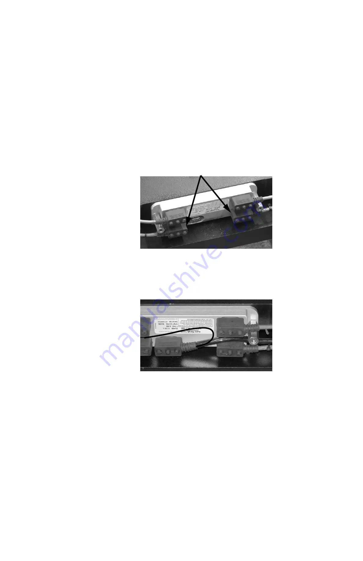
Attach all Weigh Bar cables to the junction box as shown in Figure 10.14. Th
top Weigh Bars are attached to the connectors closest to the front plate of the 
scale carriage. 

Figure 10.14  Weigh Bar cables attached to junction box.

13.

Attach the interface cable. Route the cable as shown in Figure 10.15. The 
photo shows the exit path if the cable is exiting at the top center or on the right 
side of the carriage. The drawn line shows the cable routing if you want the 
cable exit on the left side of the carriage. Pay close attention that the cable is 
routed between the Weigh Bar connectors and under the standoff. 

Figure 10.15  Interface cable routing

14.

Attach the jbox retainer plate to the standoffs and tighten the two bolts.

15.

Place the scale carriage on the forklift, add the forks and pick up a loaded 
pallet.

16.

With a helper, block the back of the forks with a wedge shaped piece of wood 
while lowering the carriage so the scale will tilt forward when lowered.

17.

Lower the scale so that it disengages from the forklift carriage.

Top Weigh Bar connectors

Содержание FLI 225

Страница 1: ...FLSC 05 Forklift Scale with FLI 225 Instrument Service Manual original instructions AWT 35 500234 Issue AK CONFIDENTIAL ...

Страница 2: ...f a two dimensional work and the making of a copy in two dimensions of a three dimensional work stored in any medium by electronic means or transmitted in any form or by any means including electronic mechanical broadcasting recording or otherwise without the prior written consent of the copyright owner under license or as permitted by law This publication was correct at the time of going to print...

Страница 3: ...erview of the Menus and Modules 15 Accessing and Exiting the Menus 16 Overview of the Modules 17 User Settings 17 About FLI 225 17 Audit Trail Viewer 17 Audit Trail Counter 17 Diagnostics Manager 17 Supervisor Settings 18 Setup Manager 18 Chapter 4 User Settings Module 19 Time 19 Date 20 Display Contrast 20 Seal Status 21 Chapter 5 About FLI 225 Module 22 Chapter 6 Audit Trail Viewer Module 23 Vie...

Страница 4: ...2 Country Code 73 Miscellaneous 74 Inputs 74 Reset System 75 Passwords 76 Display 76 Time Date 77 Enable or Disable Keys 77 Diagnostics Tools 78 Chapter 10 Extras 79 Making a Ramp for Tilting the Forklift 79 Calculating New Lift Capacity 80 Class II 5 000 lb Models 81 Resistance Test for FLSC Weigh Bars 81 Replacing Weigh Bars on the FLSC 05 Carriage 82 Disassembly of the Carriage 82 Reassembly 85...

Страница 5: ...FLSC 05 w FLI 225 Instrument Service Manual 5 Carriage Assembly Parts List 105 Exploded View of FLI 225 AWT05 500348 106 FLI 225 Instrument Parts List Options 107 Menu Maps 108 ...

Страница 6: ...dded Section 6 3 Audit Trail Counter with details Added section on determining if calibration is required for EU Section 9 1 2 which includes 2 Calibration tests with weights in KG starting on p 40 Added tables showing default settings for ranges depending on country configuration on p 62 63 Added new print tokens to table on p 69 Updated drawing and dimensions of ramps to include metric measureme...

Страница 7: ... the key being described This applies to hard keys and onscreen or soft keys Displayed messages appear in bold italic type and reflect the case of the displayed message 1 1 2 Special messages Examples of special messages you will see in this manual are defined below The signal words have specific meanings to alert you to additional information or the relative level of hazard DANGER THIS IS A DANGE...

Страница 8: ...is is a Note symbol Notes give additional and important information hints and tips that help you to use your product DANGER RISK OF ELECTRICAL SHOCK NO USER SERVICEABLE PARTS REFER TO QUALIFIED SERVICE PERSONNEL FOR SERVICE IMPORTANT This equipment must be routinely checked for proper operation and calibration Application and usage will determine the frequency of calibration required for safe oper...

Страница 9: ...al device pursuant to Part 15 of the FCC Rules These limits are designed to provide reasonable protection against harmful interference when the equipment is operated in a commercial environment This equipment generates uses and can radiate radio frequency energy and if not installed and used in accordance with the instruction manual may cause harmful interference to radio communications Operation ...

Страница 10: ...10 FLSC 05 w FLI 225 Instrument Service Manual ...

Страница 11: ...FLSC 05 w FLI 225 Instrument Service Manual 11 1 FCC and EMC Declarations of compliance ...

Страница 12: ...r to chapter 9 App Selection on page 72 2 1 Front Panel and Keys The 5 hard keys and 4 softkeys on the front panel of the FLI 225 have multiple functions Figure 2 1 FLI 225 Front Panel Table 2 1 Key Definitions Reference Key Name Key Function s 1 TARE Tare the weight on the scale for net weighing Factory default for this key is OFF See Enable or Disable Keys on page 77 2 STANDBY Turn the instrumen...

Страница 13: ...keys 6a 6d are shown 6a Esc softkey Abort a procedure or return to previous menu 6b Up Arrow softkey Scroll up from zero and then forward through the alphabet 6c Down Arrow softkey Scroll backwards from zero and then backwards through the alphabet 6d Enter softkey Accept an entry Table 2 1 Key Definitions Reference Key Name Key Function s If you make a mistake press the SELECT key to backspace and...

Страница 14: ...nt ZERO key Mimics the function of the ZERO key on the FLI 225 instrument Underload Indicates that the scale is outside the gross zero range under weight Overload Indicates that the scale is overloaded Over Angle Indicates that the scale is tipped right left forward or back too far Y Indicates that the instrument is set to FLSC Wireless and is communicating wirelessly with the carriage Y Indicates...

Страница 15: ... Menu default password 911 Supervisor Management Menu default password 1793 Admin Management Menu default password 522 Figure 3 1 is a table explaining the module access granted by the different passwords There are eight modules and four of them appear in all four menus A module remains the same no matter which menu it appears in Each successive menu shown in Figure 3 1 accesses more modules This ...

Страница 16: ...ay shows the available modules 4 Press the Up or Down Arrow softkey to move to the desired module 5 Press the Enter softkey to access the highlighted module 6 Make any necessary change s to the selected module 7 Press the Esc softkey to return to the previous screen 8 Press the Esc softkey as necessary to exit to normal operating mode The instrument saves any changes and reboots into normal operat...

Страница 17: ...nt with the dates and times of the changes See chapter 6 Audit Trail Viewer Module for more information 3 2 4 Audit Trail Counter The Audit Trail Counter is available in all four menus and shows the number of times the calibration information has changed 3 2 5 Diagnostics Manager The Diagnostics Manager module is available in the Diagnostics Supervisor and Admin Management menus It provides a way ...

Страница 18: ...eight l Scale configure various scale metrology items including m Units set calibration units enable units of measure m Settings configure capacity divisions and carriage type m Filter set various filtering components m Motion AZT configure motion and AZT m Auto Tare Clear enable or disable auto tare clear m Ranges set ranges for overload underload zero range center of zero zero band auto print an...

Страница 19: ...r Settings 2 After completing all changes press the Esc softkey to exit The changes are saved and the instrument reboots into normal operating mode 4 1 Time Regardless of the format that the time is displayed enter the time in 24 hour format If you do not know the seconds value you can leave it blank and it will continue from when you started 1 Access the User Settings module 2 Press the Up or Dow...

Страница 20: ...rast To allow for various lighting environments you can adjust the display contrast settings 1 Access the User Settings module 2 Press the Up or Down Arrow softkey as necessary to highlight Display Contrast 3 Press the Enter softkey Figure 4 4 Sample Display Contrast Screen 4 Select a value between 1 and 5 using the Up or Down Arrow softkeys Default setting is 3 5 Press the Enter softkey to accept...

Страница 21: ... or unsealed by following these steps 1 Access the User Settings module 2 Press the Up or Down Arrow softkey as necessary to highlight Seal Status 3 Press the Enter softkey The current status sealed or unsealed is displayed Figure 4 5 Sample Seal Status Screen 4 Press the Esc or Enter softkey to return to the previous module The display returns to the User Settings screen The default setting is un...

Страница 22: ...ee Overview of the Menus and Modules on page 15 1 Access the User Management menu as explained on page 16 using password 111 2 Press the Down Arrow softkey as necessary to highlight About FLI 225 3 Press the Enter softkey The instrument briefly shows the current firmware version and then the part number for the instrument Figure 5 1 Sample Firmware Version left and Part Number right After displayi...

Страница 23: ... highlight Audit Trail Viewer 3 Press the Enter softkey The audit trail is displayed Figure 6 1 Sample Audit Trail 4 Press the Up or Down Arrow softkey as necessary to move through the entries and pages 5 After viewing printing the audit trail press the Esc softkey The instrument returns to the previous screen 6 Press the Esc softkey to exit to normal operating mode 6 1 View Audit Trail Record To ...

Страница 24: ...has been calibrated It is available when you enter any of the passwords however this section assumes the individual is entering password 111 For more information on how to access the menus see Overview of the Menus and Modules on page 15 1 Access the User Management menu as explained on page 16 using password 111 2 Press the Down Arrow softkey as necessary to highlight Audit Trail Counter 3 Press ...

Страница 25: ... module is displayed as shown in Figure 7 1 Figure 7 1 Screen 1 left and 2 right of Diagnostics Manager 3 Press the Up or Down Arrow softkey to highlight an option 4 Press the Enter softkey to select the highlighted option 5 Test the option as necessary 6 After completing the diagnostics press the Esc softkey to return to the Diagnostics Management menu accessed in step 1 7 1 Communications Select...

Страница 26: ...t of communications ports 5 Press the Esc softkey to return to the Diagnostics Manager module Test Handshaking You can also perform a loopback test on COM 3 to verify that handshaking is working properly For information on enabling handshaking see Handshake on page 65 1 To test Handshaking you must also jumper CTS and RTS 2 Perform the communications test as described on page 25 You will get a mes...

Страница 27: ...ill flash the model name in standard display followed by inverse highlighted and finally a solid black screen and will repeat until F1 or F4 is pressed 2 Press the Enter softkey Figure 7 5 Test Screens 3 Press either the F1 or F4 key to end the test and return to the Diagnostics Manager module 7 4 Analog Option Card The Analog Option Card test is not available on the FLSC 05 digital system Refer t...

Страница 28: ...100 Status Screens Wired on left Wireless on right 7 5 2 View FLJ 100 Counts 1 From the FLJ 100 module press the Down Arrow softkey as necessary to highlight View FLJ 100 Counts 2 Press the Enter softkey to display the Scaled Counts Any reference to right left forward backward top or bottom is from the driver s point of view Figure 7 8 Sample FLJ 100 Counts 3 Press the ZERO key to zero the counts ...

Страница 29: ...nostics Manager module 7 7 Seal Switch This instrument has a Category 3 audit trail For locations requiring a physical seal there is a seal switch located at S1 on the communications power supply board Select Seal Switch from the Diagnostics Manager module to view the current status sealed or unsealed For information on sealing or unsealing the instrument see Change Seal Status on page 35 7 8 Erro...

Страница 30: ...nitions Error Definition UNDERLOAD ERROR The weight on the carriage has gone below the set negative of capacity OVERLOAD ERROR The weight on the carriage has gone above the set positive of capacity DRIFT ERROR Zero Tracking has removed an accumulated weight beyond the set positive or negative of capacity FLJ COMM ERROR Communication with the FLJ 100 or FLW 100 has been lost FLJ CHANGE ERROR An FLJ...

Страница 31: ...8 1 Figure 8 1 Supervisor Settings Module 3 Press the Up or Down Arrow softkey to highlight an option 4 Press the Enter softkey to select the highlighted option 5 Configure the option as necessary 6 After completing configurations press the Esc softkey to return to the Supervisor Management menu 8 1 Zero Band 1 Select Zero Band from the Supervisor Settings module to view or change the Zero Band va...

Страница 32: ...lect Prompt Timeout from the Timeouts screen 2 Scroll in the timeout value in seconds using the data entry procedure 3 Press the Enter softkey once the value is correct The instrument returns to the Timeouts screen 4 Press the Esc softkey to return to Supervisor Settings 8 2 2 Shutdown Timer By default the shutdown timer is set to 4 hours You can change the shutdown timer to 30 minutes 1 hour 2 ho...

Страница 33: ...ocedure to scroll in any information to help identify the forklift such as a serial number 3 Press the Enter softkey The information is stored and the instrument returns to the Identification module Scale ID 1 Select Scale ID from the Identification module 2 Use the data entry procedure to scroll in the identification number such as a serial number carriage type etc for the scale 3 Press the Enter...

Страница 34: ...et span perform corner and angle calibration See Calibrate the FLSC 05 with FLI 225 on page 36 for details Scale Select Scale to configure the various components of Units Settings Filter Motion AZT Ranges and System See Scale on page 55 for details Communications Select Communications to configure the various communications ports SeeCommunications on page 64 for details Print Strings Select Print ...

Страница 35: ...n 4 If the status is unsealed skip to step 8 Otherwise continue with the following 5 Remove the back panel of the instrument 6 Press the seal switch located at S1 on the communications power supply board The status changes from sealed to unsealed 7 Replace the back panel 8 Press the Esc or Enter softkey to return to the previous module The display returns to the User Settings screen 9 Press the Es...

Страница 36: ...ess the various calibration procedures as shown below Figure 9 3 Calibration Main Screen l When finished with calibration press the Esc softkey to return to the top of the Setup Manager screen l Press the Esc softkey again to return to the Admin Management menu Gravity compensation Gravity compensation is only done once if necessary when the scale is put into service For full details see Gravity C...

Страница 37: ...e if you used 2000 lbs for full weight span weight you will need to use 1000 lbs for half weight 9 1 1 Determining if Calibration is Needed NA Calibration of the FLSC 05 with FLI 225 may be required when l The system fails one of the following calibration tests l A Weigh Bar is replaced l The FLI 225 is replaced l The FLJ 100 is replaced Calibration Test Method 1 NA Calibration Test 1 uses 1000 po...

Страница 38: ...e 51 using a minimum of 2000 pounds for the span weight 11 Upon completion reconfigure the indicator to 5 lb divisions and AZT ON Calibration Test Method 2 NA Calibration Test 2 uses a 500 pound certified test weight to establish if the Avery Weigh Tronix legal for trade forklift scale requires recalibration The allowable variance in all instances is 1 pound Therefore any weight reading between 49...

Страница 39: ...plained on page 48 using a minimum of 500 pounds for the span weight before continuing with step 8 8 Place 500 pounds in the center of the pallet 9 Tilt the mast forward and note the weight reading 10 Tilt the mast back and note the weight reading If the system fails either step 9 or step10 perform the 16 point Angle Calibration as explained on page 51 using a minimum of 2000 pounds for the span w...

Страница 40: ...sturdy pallet on the forks 5 With the forks raised press the ZERO key to zero the scale 6 Place 500 kg in the center of the pallet If the system fails this test perform a Zero and Span operation as explained on page 46 using a minimum of 500 kg for the span weight before continuing with step 7 7 Place 500 kg on each of the corners in succession noting the weight reading for each corner If the syst...

Страница 41: ...e span weight before continuing with step 7 7 Place 200 kilograms on each of the corners in succession noting the weight reading for each corner If the system fails this test perform the Corner Calibration as explained on page 48 using a minimum of 200 kg for the span weight before continuing with step 8 8 Place 200 kilograms in the center of the pallet 9 Tilt the mast forward and note the weight ...

Страница 42: ...rieve the stored calibration coefficient information from the junction box The parameters are saved and the instrument returns to normal operating mode 4 Press the ZERO key if the weight displayed is not zero 5 Proceed to one of the calibration tests on pages 38 through 41 If the screen in Figure 9 6 does not display on power up the FLI 225 that is connected to the system was set to Factory Defaul...

Страница 43: ...rieve the stored calibration coefficient information from the FLI 225 The parameters are saved and the instrument returns to normal operating mode 3 Press the ZERO key if the weight displayed is not zero 4 Proceed to one of the calibration tests on pages 38 through 41 This option is not available for instruments with EU configuration The instrument will display dashes and the message Calibration R...

Страница 44: ...ructions for calculating the local gravity factor continue from the previous section In order to calculate the gravity factor you will need the latitude and altitude for the destination 3 Select Calculate Local g Factor The instrument prompts you to enter the local latitude Figure 9 10 Calculate Local Gravity Screen 1 4 Scroll in the local latitude using the data entry procedure If you know the lo...

Страница 45: ...ter softkey to return to the Gravity Compensation list 9 Press the Esc softkey to return to the Calibrate screen Key in Known Gravity Factor If you know the gravity factor for the place of installation you can save several steps 1 From the Gravity Compensation Menu select Key In View Local g Factor The current gravity factor is displayed Figure 9 13 Gravity Factor Key in Screen 2 Scroll in the new...

Страница 46: ...alue other than zero while processing Figure 9 14 Zero in Process The zero value is stored after processing 4 Press the Enter or Esc softkey to return to the Calibrate screen when prompted 9 1 5 Span 1 Select Span from the Calibrate menu 2 Using the data entry procedure scroll in the calibration weight if other than the default Figure 9 15 Key in Calibration Weight The Cal Weight value span weight...

Страница 47: ...ess The span value is stored after processing 5 Press the Enter or Esc softkey when prompted Span calibration is complete and the instrument returns to Calibrate 9 1 6 FLSC Calibration Select FLSC Calibration from the Calibrate screen and the following screen is displayed Figure 9 18 FLSC Calibration Screen Corner Calibration helps the Weigh Bars work together If you will be performing an Angle Ca...

Страница 48: ...ght Rear 1 Select Set View Corner Points from the Corner Calibration menu The Set View Corner Points screen is displayed with Pt 1 Right Rear highlighted Figure 9 20 Set View Corner Points Screen 2 Press the Enter softkey Table 9 1 Corner Points Defined Point Description Pt 1 Right Rear Place weight on the rear right corner of the pallet Pt 2 Left Rear Place weight on the rear left corner of the p...

Страница 49: ...nts and returns to the Set View Corner Points screen 6 Remove the weight except for the deadload Pt 2 Left Rear Pt 4 Right Front The instructions for points 2 through 4 are the same as those for point 1 and are described in this section The instructions continue from the previous section 7 From the Set View Corner Points screen press the Down Arrow softkey to highlight the next point Pt 2 Left Rea...

Страница 50: ...r Calibration screen 14 Proceed to Fit Corner Points Fit Corner Points After completing the corner calibration you must fit the points 1 Select Fit Corner Points from the Corner Calibration screen 2 Press the Yes softkey to fit the corner points The screen displays Fit Complete and displays a weight 3 Press the Esc or Enter softkey to return to the Corner Calibration menu 4 Press the Esc softkey t...

Страница 51: ...le calibration 1 Select Cal Full Weight from the Angle Calibration module 2 Scroll in the new value using the data entry procedure 3 Press the Enter softkey The instrument returns to the Angle Calibration menu 4 Select Cal Half Weight from the Angle Calibration module 5 Repeat steps 2 and 3 The instrument returns to the Angle Calibration menu 6 Proceed to Set View Angle Points Set View Angle Point...

Страница 52: ...Sixteen Points Points 1 5 Points 6 10 Points 11 15 Point 16 No Weight Half Weight Full Weight Half Weight Level Level Level Level Roll Left 5 Roll Left 5 Roll Left 5 Roll Right 5 Roll Right 5 Roll Right 5 Pitch Forward Pitch Forward Pitch Forward Pitch Backward Pitch Backward Pitch Backward Any reference to Right Left Forward or Backward is from the driver s point of view In the illustration below...

Страница 53: ...trument stores the value and returns to the Set View Angle Points screen 8 Press the Down Arrow softkey to highlight Pt 3 No Wt Roll Right 9 Roll the forklift 5 degrees to the right 10 Press the Store softkey The instrument stores the value and returns to the Set View Angle Points screen 11 Press the Down Arrow softkey to highlight Pt 4 No Wt Pitch Forward 12 Press the Enter softkey 13 Tilt the fo...

Страница 54: ...eed to the section on full capacity Full Weight Points 11 15 The process of acquiring the full weight values is the same as described in the previous sections except you will use the full weight value It is assumed that points 1 through 10 have been set 1 Add sufficient weight until reaching the full weight value 2 Perform all five full weight calibration points as prompted The procedure is the sa...

Страница 55: ...o the top of the Setup Manager module 7 Select another item from the Setup Manager or press the Esc softkey to return to the top of the Admin Management menu 9 2 Scale 1 Select Scale from the Setup Manager module and the following is displayed Figure 9 27 Scale Module Pages 1 and 2 2 Select the item to configure from the Scale module 3 When finished changing the scale properties press the Esc soft...

Страница 56: ...om unit of measure such as a ton follow these steps 1 Select Custom from the Units screen The Custom menu displays Figure 9 29 Custom Units Menu 2 Select Custom Unit 3 Press the Up or Down Arrow softkey to select On 4 Press the Enter softkey The change is made and the instrument returns to the Custom module 5 Select Custom Name 6 Scroll in a new name for the custom unit of measure using the Data E...

Страница 57: ... the Esc softkey again to return to the Scale module 9 2 2 Settings 1 Select Settings from the Scale Module and the following screen is displayed Figure 9 30 Settings Module with Defaults 2 After defining the settings press the Esc softkey to exit and return to the Scale Module Each item is explained below Capacity By default the capacity is 5000 lb 1 From the Settings screen select Capacity 2 Scr...

Страница 58: ...FLI 225 This is an all digital system QTLTSC refers to the analog QTLTSC carriage This is an analog scale with angle sensing for legal for trade operation and an interface cable to the FLI 225 QTLTS refers to the analog QTLTS carriage This is an analog scale with an interface cable to the FLI 225 2 Press the Enter softkey to accept the choice and return to Settings 9 2 3 Filtering Filtering is use...

Страница 59: ...between 0 and 10 3 Press the Enter softkey The constant is stored and the instrument returns to the Filter screen Threshold The purpose of the Threshold is so the instrument will respond quickly to large weight changes Threshold is the amount of weight change in calibration units beyond which the filter will be temporarily disabled For example if you set this to 10 lbs a weight change over 10 poun...

Страница 60: ...turns to the Motion AZT module AZT div 1 Select AZT div from the Motion AZT to display the list of divisions The default setting is 3 2 Press the Up or Down Arrow softkey to select the appropriate number of divisions from the list This division size defines a range above and below zero When the weight is within this range for the number of seconds set in AZT sec 50 of the weight will be zeroed The...

Страница 61: ... Tare Clear Off from the Scale module 2 Select either On or Off The change is made and the instrument returns to page 2 of the Scale module 9 2 6 Ranges 1 Select Ranges from the second page of the Scale Module to display these screens Figure 9 33 Sample Ranges Module 2 Select the range you wish to change from the Ranges Module Refer to the appropriate table for available ranges and default values ...

Страница 62: ...05 20 Zero Range This is the amount of weight you can zero off Zeroing off weight reduces the scale capacity by the amount of weight zeroed off 0 100 100 Center of Zero This affects how the zero indication will operate Any weight within of your choice for the zero point will cause the display to show the center of zero annunciator 0 0 25 0 50 divisions 0 25 divisions Zero Band This determines how ...

Страница 63: ... the amount of weight you can zero off Zeroing off weight reduces the scale capacity by the amount of weight zeroed off 0 100 100 Center of Zero This affects how the zero indication will operate Any weight within of your choice for the zero point will cause the display to show the center of zero annunciator 0 0 25 0 50 divisions 0 25 divisions Zero Band This determines how close to actual zero the...

Страница 64: ...s from the Setup Module to display the Communications module Figure 9 34 Communications Module 2 Select the appropriate port The configurable options are displayed Figure 9 35 Com Port Screens 1 3 3 Configure the port as necessary See configuration options on the following pages 4 After configuring the port s press the Esc softkey to exit and return to the Setup Module When connected to a digital ...

Страница 65: ...nd the corresponding results l Broadcast Choose Broadcast to continually output broadcast data from the instrument to a peripheral device l Remote Display Choose Remote Display to configure the COM port for use with the FLR 100 remote display Baud Select Baud to choose from the available baud rates 300 1200 2400 4800 9600 19200 38400 57600 115200 Select one and press the Enter softkey to activate ...

Страница 66: ...default value is Off Update Rate Select Update Rate and choose 1 2 5 or 10 updates per second The default is 1 Make your selection and press the Enter softkey to accept it and return to the previous screen 9 4 Print Strings Select Print Strings from the Setup Manager module to customize what information is included on reports transaction records etc using up to 10 print strings and defining which ...

Страница 67: ... screen to display the list of available print strings Figure 9 37 Print String Editor page 1 of 3 2 Select the string you need to change The configurable options for the selected print string are displayed Refer to the figure and table below to help you move around the editor Figure 9 38 Sample Print String Detail with Configuration Keys ...

Страница 68: ...e current print string details to a printer or other peripheral 3 Press the SELECT key to move to the previous character This does NOT delete the previous character 4 Press the ZERO key to move to the next character 5 Press the Enter softkey F4 to accept the entry and return to the list of strings 6 Press the Down Arrow softkey F3 to scroll down through the HEX and DEC values 7 Press the Up Arrow ...

Страница 69: ... 0xAD WST Weight Steady 200 0xC8 DSP Print Displayed Weight 208 0xD0 DBF Database Field 1 ID 2 Scale Carriage ID 3 Device ID 4 Site ID 5 Forklift ID 6 Operator ID 215 0xD7 NULL Null Token 216 0xD8 ACT Send the active value G gross N net T Tare 229 0xE5 PAC Pitch Angle Counts 230 0xE6 RAC Roll Angle Counts 231 0xE7 PAD Pitch Angle Degrees Value 232 0xE8 RAD Roll Angle Degrees Value 233 0xE9 HRW Hig...

Страница 70: ...70 FLSC 05 w FLI 225 Instrument Service Manual Chart of ASCII Characters ...

Страница 71: ...rings and the order they are sent are displayed Figure 9 40 Sample Strings to Print for Print Key 3 Select the step you wish to change A list of available print strings is displayed Figure 9 41 Available Print Strings page 1 of 3 4 Select one of the available print strings to add the string to the mode and return to the previous screen Figure 9 42 Updated Strings to Print Screen 5 Repeat steps 2 t...

Страница 72: ...ate transactions and print them later or print accumulator reports Expanded Expanded mode builds on the Classic w Accumulator mode and activates the ID Pallet and Oper softkeys 2 Select the application that best suits your customer s needs 3 If prompted to default the print strings press the Yes softkey to set the print strings back to their defaults or press the No softkey to keep any changes mad...

Страница 73: ...verride the setting which was made in Country Code Table 9 7 Default Settings by Region Setting North America NA Default Europe EU Defaults Gravity Compensation 9 8043 9 8043 Calibration Unit lb kg Enabled Unit s lb kg Weight Capacity 5000 lb 2500 kg Weight Division 5 lb 2 kg Calibration Full Weight 4000 lb 2000 kg Calibration Half Weight 2000 lb 1000 kg Gross Zero Band 50 lb 10 divisions 20 kg 10...

Страница 74: ...press the Esc softkey to exit and return to the Setup Module 9 7 1 Inputs 1 Select Inputs from the Miscellaneous module to display the Inputs screen Figure 9 45 Default Inputs Screen 2 From the Inputs screen select either Input 1 or Input 2 The remote input options for the input are displayed Figure 9 46 Input Options 3 Select the option you wish to assign to the selected input The change is made ...

Страница 75: ...eset System 1 Select Reset System from the Miscellaneous module to display the following screen Figure 9 47 Reset System Screen l Reset All Accumulators clears the accumulators but all other settings will remain l Reset Configuration sets all configuration settings EXCEPT calibration back to factory defaults including Country Code and Print Strings l Reset Entire System will set the instrument bac...

Страница 76: ...neous module to access the Display screen Figure 9 49 Display Screen 2 Select Update Rate Hz to access the list of available update rates 3 Change the update rate to 1 2 5 or 10 Hz as necessary The default is 5 The change is made and the instrument returns to the Display screen 4 Select Separator from the Display screen to display the available options decimal point or comma 5 Select the decimal s...

Страница 77: ...e Time Date screen select Date to change the way dates are displayed 6 Select either MMDDYYYY 2 digit month 2 digit day 4 digit year or DDMMYYYY 2 digit day digit month 4 digit year The default setting for North America is MMDDYYYY The change is made and the instrument returns to Time Date 7 Press the Esc softkey to return to the Miscellaneous module 9 7 6 Enable or Disable Keys 1 Select Key Enabl...

Страница 78: ...ostics Screens 2 Select the option you wish to enable or disable 3 Select On enable or Off disable as necessary The changes are made and the instrument returns to the Diagnostics module 4 Press the Esc softkey to return to the Miscellaneous module The Over Trigger and Under Trigger values are shown for reference only and can not be changed in this module The values shown reflect the ranges set in ...

Страница 79: ... plywood Total height is 3 inches 76 2 mm Table 10 1 Ramp board dimensions Board H W L in inches A 0 5 in 12 7 mm 8 in 203 2 mm 24 in 609 6 mm B 0 5 in 12 7 mm 8 in 203 2 mm 22 in 558 8 mm C 0 5 in 12 7 mm 8 in 203 2 mm 20 in 508 0 mm D 0 5 in 12 7 mm 8 in 203 2 mm 18 in 457 2 mm E 0 5 in 12 7 mm 8 in 203 2 mm 16 in 406 4 mm F 0 5 in 12 7 mm 8 in 203 2 mm 14 in 355 6 mm ...

Страница 80: ...t lifting capacity of your forklift with a scale attached Refer to the figure below for the dimensions Figure 10 1 Formula Dimensions for Calculating New Lift Capacity It is the customer s responsibility to contact their forklift manufacturer distributor with this information to obtain the new ID plate No scale installed Scale installed l A Forklift Capacity in pounds l B Inches from front wheel c...

Страница 81: ...4 0 346 lb 2 0 4 0 36 0 365 lb 2 0 4 0 37 0 369 lb 2 0 4 0 38 0 373 lb 2 0 4 0 40 0 396 lb 2 0 4 0 42 0 404 lb 2 0 4 0 Pins Wires Reading Tolerance in Ohms 1 to 2 ORG to RED _____________ 996 to 1004 1000 3 to 4 YEL to BRN _____________ 998 to 1002 1000 6 to 7 GRN to BLK _____________ 1074 to 1087 1080 7 to 8 BLK to BLU _____________ 1047 to 1053 1050 1 to 6 ORG to GRN _____________ 785 to 795 790...

Страница 82: ... this disassembly and reassembly procedure is a two person task Jam nuts are torqued to 500 ft lbs so removal requires extra force and caution Use a 3 4 or 1 drive socket and the method described below to secure the scale for disassembly assembly 1 Leave the forks on the scale with a loaded pallet on them 2 Remove the lower hooks and disconnect the scale interface cable 3 With a helper block the b...

Страница 83: ...Figure 10 3 Bolts to remove 7 Remove the junction box guard by removing the bolts pointed out in Figure 10 3 8 Remove the junction box retainer plate bolts shown in Figure 10 4 and remove the retainer plate Figure 10 4 Junction box retainer plate and bolts 9 Disconnect all the connectors from the junction box Cable egress guard bolts 7 16 Jbox guard bolts 7 16 recessed ...

Страница 84: ...orks and lower the scale carriage onto the edge of a sturdy pallet and back the forklift away 14 With assistance from other people or a hoist lower the scale onto its front face on the pallet 15 Remove the jam nuts and the hardened washers from the Weigh Bars 16 With assistance from other people or a hoist remove the rear carriage plate from the front carriage plate being careful not to damage the...

Страница 85: ...s position See Figure 10 7 for an illustration of how the Weigh Bars should be connected to the FLJ 100 Figure 10 7 FRONT label positions and FLJ 100 illustration View from below With the top Weigh Bars labeled FRONT reassemble the carriage by reversing the disassembly steps Pay close attention to the following notes 1 Place the new Weigh Bar in position and check its rotation orientation Be sure ...

Страница 86: ...ure 10 8 Cable routing and cable ties 4 Be sure to cable tie the cables to the shield in a way that prevents the cables from contacting the Weigh Bar bolts See Figure 10 9 Figure 10 9 Space must exist between the cable and the bolt and shield Cable routing on the left side of the carriage Left side is from driver s perspective Cable routing on the right side of the carriage Right side is from driv...

Страница 87: ...Follow the pattern shown in Figure 10 10 Figure 10 10 Weigh Bar bolt tightening pattern 7 Using a hoist and strap or plenty of manpower slowly lower the back of the carriage over the front lining up the Weigh Bars with their associated holes in the back plate Be sure to keep the Weigh Bar cables and ends positioned so they are not pinched as the two pieces are brought together The cables should ex...

Страница 88: ...ger tight See Figure 10 13 Figure 10 13 Hardened washer and jam nut 9 With help stand the carriage assembly up on the pallet and move the cable shields between the carriage halves with your fingers until the tab on each corner of each shield engages in the holes in the back carriage plate Step 9 is important to avoid damaging the cable shield and for proper function of the scale ...

Страница 89: ...Figure 10 15 The photo shows the exit path if the cable is exiting at the top center or on the right side of the carriage The drawn line shows the cable routing if you want the cable exit on the left side of the carriage Pay close attention that the cable is routed between the Weigh Bar connectors and under the standoff Figure 10 15 Interface cable routing 14 Attach the jbox retainer plate to the ...

Страница 90: ...he cable egress and jbox guards 21 The scale is now ready to be reinstalled on the forklift 10 4 3 Tightening Procedure To tighten the jam nut to 500 ft lbs you can use two techniques One Buy a 500 ft lb torque wrench and use this to torque the nut Two Torque the nut to 50 ft lbs and then with a 3 4 or 1 drive socket turn the nut 1 6th of a turn This will be very close to 500 ft lbs See the Figure...

Страница 91: ...ional FLW 100 kit The kit is made up of these parts 1 Carriage transceiver 2 FLI 225 instrument transceiver 3 Battery guard 4 Battery pack 5 Battery charger See FLI 225 Instrument Parts List Options on page 107 for a more detailed list of available parts 1 2 3 4 5 The kit is pre configured at the factory If you choose to change the setup you must configure the radio using a PC with the FLW 100 Upd...

Страница 92: ...figure 10 18 Figure 10 18 Bolts to remove 2 Remove the junction box guard by removing the bolts pointed out in figure 10 18 3 Remove the junction box retainer plate bolts shown in figure 10 19 and remove the retainer plate Figure 10 19 Junction box retainer plate and bolts 4 Disconnect the interface cable from the junction box and from the back of the FLI 225 5 Clip all cable ties and remove the i...

Страница 93: ...Figure 10 20 Installing carriage transceiver 7 Press the transceiver into the slot About 1 inch of the housing will extend outside the carriage plate Place the two supplied screws and brass washers into the holes on each side of the transceiver to firmly hold it in place See figure 10 21 Figure 10 21 Carriage transceiver and hold down bolts and washers 8 Pass both connectors down and between the c...

Страница 94: ... egress guard and tighten the two bolts Reference figure 10 18 12 Run the power cable from the transceiver down the right side of the carriage and cover it with the cable guide plate shown in figure 10 23 Figure 10 23 Cable guide plate rear view of carriage 13 Bolt the cable guide plate in place with the two supplied bolts 14 Replace the junction box guard and tighten the two bolts through the acc...

Страница 95: ...Place the battery guard on the back plate of the carriage and place the two supplied bolts through the recesses shown in figure 10 25 through the battery guard holes and into the threaded holes in the carriage back plate Tighten to hold the battery guard firmly in place Figure 10 25 Battery guard recessed bolts 17 The power cable should exit the battery guard as shown in figure 10 26 Figure 10 26 ...

Страница 96: ...eased Figure 10 27 Sponge rubber strips 19 Connect the battery to the power cable and loop the cable inside the channel Tuck the cable and connectors inside this channel 20 Place the recessed end of the battery pack into the channel and snap the other end down until the latch snaps shut figure 10 28 shows the battery pack in place Figure 10 28 Battery pack in place view from the back of the carria...

Страница 97: ...ure 10 29 Figure 10 29 Instrument transceiver installed on the FLI 225 Your wireless carriage system is now installed There are some settings to make in the FLI 225 instrument to configure it for wireless function Ask your service representative to perform this configuration 10 5 1 Charging the Battery 1 To charge the battery release the catch as shown in figure 10 30 Figure 10 30 Battery pack cat...

Страница 98: ...m block diagram for location of COM ports Connect the DB 9 connector to the scanner The COM port must be configured for scanner operation See Communications on page 64 for instructions on configuring the COM port Figure 10 32 Scanner Cable and Color Codes 10 7 RM 200 Connection The RM 200 part number AWT05 500691 allows the FLI 225 to perform a variety of communications functions wirelessly These ...

Страница 99: ...See the system block diagram on page 103 for location of COM ports 5 Replace the back plate 6 Tighten the strain relief as necessary 7 Connect the FLI 225 to the scale system 8 Reconnect the power 9 Configure the COM port according to the function required See Communications on page 64 Red TXD Green RXD Orange Power Black Ground Yellow RTS Brown CTS To FLI 225 ...

Страница 100: ...s to take the xxxxxx xxx data as the tare weight and returns G or N weight if no motion Dashes displayed if motion on scale LF M CR Returns the tare weight if no motion Dashes displayed if motion on scale LF C CR Clears the tare weight if no motion Dashes displayed if motion on scale LF U uuu CR Sets the unit of measure label to uuu Example lb_ _ space Works for lb or kg only not custom units LF D...

Страница 101: ...he indicator will respond with LF XT cutoff xxxx xx Set CR if the cutoff weight was accepted or LF XTFail CR if the cutoff weight could not be set to the value specified Cutoff 1 3 Weight limited to scale cap LF XT cutoff CR Request a cutoff trip weight The indicator will respond with LF XT cutoff xxxx xx CR where xxxx xx is the weight for cutoff number cutoff or LF XTError CR if the cutoff number...

Страница 102: ...ly that allows you to connect the probe to bare metal You should see the same voltage as in step 1 3 If this voltage does not match the scale carriage is not getting a proper ground connection to the lift truck chassis It is the technician s responsibility to fix the problem 4 To correct this problem a grounding strap wire minimum 4 AWG will need to be connected from the scale carriage to the lift...

Страница 103: ... servicing this product 11 2 FLI 225 Digital System Block Diagram To digital J box Cable Assembly Digital Scale AWT25 500176 Pinouts and Color Code Color Letter Designation Connect to Red A RCVA TB1 3 XMTA Green B RCVB TB1 4 XMTB Blue C XMTB TB1 6 RCVB Yellow D XMTA TB1 5 RCVA White E 5Vdd TB1 1 5Vdd White Orange F Load TB1 7 Load Black G Ground TB1 2 Ground Tinned leads to TB1 on Comms board See ...

Страница 104: ...104 FLSC 05 w FLI 225 Instrument Service Manual 11 3 Exploded View of FLSC 05 Carriage Assembly ...

Страница 105: ... GR5 14476 0071 1 per kit WASHER FENDER 25 1 5 OD AWT20 500622 1 per kit SPRING COMPRESSION 63 2 LB IN AWT20 500352 1 per kit PIN CARRIAGE LOCATE LTS 2 50 LG AWT20 500423 1 per kit 15 RIVET BLIND SST 42 275L MAX 14500 0022 2 16 KIT ID PLATE CAL SER 5K X 5 AWT15 500113 1 17 BOLT HEX HD 25 20 X 1 00 GR5 14476 0030 2 18 WASHER LOCK CS ZP 1 4 14474 0065 8 19 GUARD EGRESS FLSC FORMED AWT20 500420 1 20 ...

Страница 106: ...106 FLSC 05 w FLI 225 Instrument Service Manual 11 5 Exploded View of FLI 225 AWT05 500348 ...

Страница 107: ...numbers before 100201251 and part number AWT20 503844 for serial numbers after Note Item 12 Gasket Backplate FLI 225 Use part number AWT20 500356 for serial numbers before 100201251 Use AWT20 503765 for serial numbers after 100201251 Reference Number Description Part No Qty FLW 100 WIRELESS INSTRUMENT FIELD INSTALL KITS Each kit includes parts marked with an asterisk listed below FLW 100 wireless ...

Страница 108: ...I 225 Instrument Service Manual 11 7 Menu Maps Use the menu maps to help you move through the various menus and modules Click on the blue text to go to the section in the manual about that topic Figure 11 1 Setup Menu ...

Страница 109: ......

Страница 110: ...031 USA Tel 507 238 4461 Fax 507 238 4195 Email usinfo awtxglobal com www wtxweb com Avery Weigh Tronix UK Foundry Lane Smethwick West Midlands England B66 2LP Tel 44 0 8453 66 77 88 Fax 44 0 121 224 8183 Email info awtxglobal com www averyweigh tronix com ...

Отзывы: