


MDF/lDF DESIGN: DEFINITY GENERIC 2 WITH UNIVERSAL MODULES
7-9
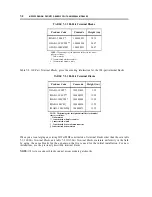
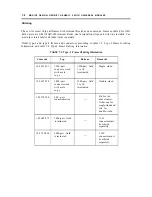
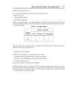
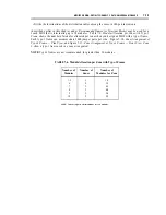
TABLE 7-4. Type-2 Frame Ordering Information
Comcode
Style
Remarks
105 689 491
2400-pair male
Single sided.
connectorized
105 689 483
2400-pair
Single sided.
field terminated
105 730 212
4800-pair male
Double sided.
connectorized
105 730 113
4800-pair
Double sided.
field terminated
DESIGNING THE MDF
Designing the MDF is a two-step process. First, determine the size of the MDF. Second, construct the
MDF. As you proceed with the design, keep in mind that function is more important than cost in
reaching a final decision since it is possible for the final installation to be inexpensive but nonfunctional.
A design that imposes operational limits to save costs may prove less desirable in the long run. Use
your site analysis to compare alternatives and arrive at the best solution in terms of both function and
cost.
Since the design of the MDF affects the design of the equipment room, be sure that your completed
design for the MDF is compatible with your equipment room plans or with the room that you have
selected for the MDF location. (When designing the MDF for a raised-floor installation, follow the
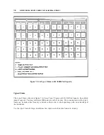
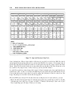
instructions under Designing the MDF for a Raised Floor in this chapter.) Figure 7-5, Overall
Equipment Wiring Plan: DEFINITY Generic 2 with Universal Modules, shows the overall equipment
wiring plan for Generic 2 with universal modules based upon the standard star configuration.
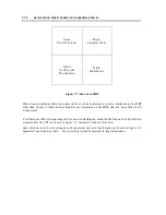
Sizing the MDF
The MDF is the largest cross-connect field of the wiring installation. It is where the incoming trunk
cables terminate and cross-connect to the trunk ports of the switch and where the building distribution
cables cross-connect to the line ports of the switch. The MDF consists of four fields: network
services/CO trunks (green), auxiliary and miscellaneous (yellow), distribution (white), and equipment
(purple).
Содержание 9601
Страница 1: ...555 104 630 Issue 2 June 1991 DEFINITY Communications SystemGeneric 2 and System 85 Wiring ...
Страница 57: ...2 34 MDF IDF DESIGN SYSTEM 85 AND DEFINITY GENERIC 2 WITH TRADITIONAL MODULES ...
Страница 67: ...3 10 ELECTRICAL PROTECTION SYSTEM 85 AND DEFINITY GENERIC 2 WITH TRADITIONAL MODULES ...
Страница 73: ...4 6 PORT PACKS DCP REPEATERS SYSTEM 85 AND DEFINITY GENERIC 2 WITH TRADITIONAL MODULES ...
Страница 85: ...6 6 OVERVIEW DEFINITY GENERIC 2 WITH UNIVERSAL MODULES ...
Страница 102: ...MDF lDF DESIGN DEFINITY GENERIC 2 WITH UNIVERSAL MODULES 7 17 Figure 7 8 Combined Trunk and Line Ports ...
Страница 112: ...MDF lDF DESIGN DEFINITY GENERIC 2 WITH UNIVERSAL MODULES 7 27 Figure 7 16 Floor Template 24 Inch Tile L472367 ...
Страница 113: ...7 28 MDF lDF DESIGN DEFINITY GENERIC 2 WITH UNIVERSAL MODULES Figure 7 17 Floor Template Cabinet Lineup L472368 I I ...
Страница 115: ...7 30 MDF lDF DESIGN DEFINlTY GENERIC 2 WITH UNIVERSAL MODULES Figure 7 18 Floor Secured Frame Installation ...
Страница 119: ...7 34 MDF lDF DESIGN DEFINITY GENERIC 2 WITH UNIVERSAL MODULES ...
Страница 123: ...8 4 ELECTRICAL PROTECTION DEFINlTY GENERIC 2 WITH UNIVERSAL MODULES ...
Страница 135: ...10 8 INSTALLATION EXAMPLE DEFINITY GENERIC 2 WITH UNIVERSAL MODULES ...
Страница 139: ...11 4 BRI DEFINITY GENERIC 2 WITH UNIVERSAL MODULES ...
Страница 174: ...GL 12 GLOSSARY ...