


CONTENTS
vii
LIST OF FIGURES
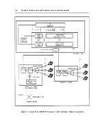
Figure 1-1. System 85 and DEFINITY Generic 2 with Traditional Module
Connectivity
Figure 2-1. Maximum Column 1500 Pairs (Five 300-Pair Terminal Blocks)
Figure 2-2. Jumper Placement
Figure 2-3. Six Type-1 Frames with 18,000-Pair Capacity
Figure 2-4. Seven Type-2 Frames with 16,800-Pair Capacity
Figure 2-5. Overall Equipment Wiring Plan
Figure 2-6. Four-Area MDF
Figure 2-7. Combined Trunk and Line Ports
Figure 2-8. Separated Trunk and Line Ports
Figure 2-9. Zone Arrangement of Type-1 Frame — Plan View
Figure 2-10. Zone Arrangement of Type-1 Frame — Front View, Zone 2
Figure 2-11. Zone Arrangement of Type-2 Frame — Plan View
Figure 2-12. Zone Arrangement of Type-2 Frame — Front View, Zone 2
Figure 2-13. Closet Cross-Connects Using Type-1 Frames
Figure 2-14. Floor Template - 18 Inch Tile (L472366)
Figure 2-15. Floor Template - 24 Inch Tile (L472367)
Figure 2-16. Floor Template - Cabinet Lineup (L472368)
Figure 2-17. Floor-Secured Frame Installation
Figure 2-18. Example of Label Filled In
Figure 3-1. Placement of Electrical Protectors on CO Side of Switch
Figure 5-1. 7-Module System Wall-Mounted on Type-1 Frame
Figure 5-2. 7-Module System Mounted on Self-Supporting Type-1 Frame, Front
Figure 5-3. 7-Module System Mounted on Self-Supporting Type-1 Frame, Rear
Figure 5-4. 7-Module System Mounted on Self-Supporting Type-2 Frame, Front
Figure 5-5. 7-Module System Mounted on Self-Supporting Type-2 Frame, Rear
Figure 7-1. Maximum Column 1500 Pairs (Five 300-Pair Terminal Blocks)
Figure 7-2. Jumper Placement
Figure 7-3. Six Type-1 Frames with 18,000-Pair Capacity
Figure 7-4. Seven Type-2 Frames with 16,800-Pair Capacity
1 - 6
2 - 3
2 - 4
2 - 6
2 - 7
2-10
2-15
2-16
2-17
2-19
2-19
2-21
2-21
2-23
2-26
2-27
2-28
2-30
2-33
3-3
5-4
5-4
5-5
5-6
5-6
7-3
7-4
7-6
7-7
Содержание 9601
Страница 1: ...555 104 630 Issue 2 June 1991 DEFINITY Communications SystemGeneric 2 and System 85 Wiring ...
Страница 57: ...2 34 MDF IDF DESIGN SYSTEM 85 AND DEFINITY GENERIC 2 WITH TRADITIONAL MODULES ...
Страница 67: ...3 10 ELECTRICAL PROTECTION SYSTEM 85 AND DEFINITY GENERIC 2 WITH TRADITIONAL MODULES ...
Страница 73: ...4 6 PORT PACKS DCP REPEATERS SYSTEM 85 AND DEFINITY GENERIC 2 WITH TRADITIONAL MODULES ...
Страница 85: ...6 6 OVERVIEW DEFINITY GENERIC 2 WITH UNIVERSAL MODULES ...
Страница 102: ...MDF lDF DESIGN DEFINITY GENERIC 2 WITH UNIVERSAL MODULES 7 17 Figure 7 8 Combined Trunk and Line Ports ...
Страница 112: ...MDF lDF DESIGN DEFINITY GENERIC 2 WITH UNIVERSAL MODULES 7 27 Figure 7 16 Floor Template 24 Inch Tile L472367 ...
Страница 113: ...7 28 MDF lDF DESIGN DEFINITY GENERIC 2 WITH UNIVERSAL MODULES Figure 7 17 Floor Template Cabinet Lineup L472368 I I ...
Страница 115: ...7 30 MDF lDF DESIGN DEFINlTY GENERIC 2 WITH UNIVERSAL MODULES Figure 7 18 Floor Secured Frame Installation ...
Страница 119: ...7 34 MDF lDF DESIGN DEFINITY GENERIC 2 WITH UNIVERSAL MODULES ...
Страница 123: ...8 4 ELECTRICAL PROTECTION DEFINlTY GENERIC 2 WITH UNIVERSAL MODULES ...
Страница 135: ...10 8 INSTALLATION EXAMPLE DEFINITY GENERIC 2 WITH UNIVERSAL MODULES ...
Страница 139: ...11 4 BRI DEFINITY GENERIC 2 WITH UNIVERSAL MODULES ...
Страница 174: ...GL 12 GLOSSARY ...