


MDF/lDF DESIGN: DEFINITY GENERIC 2 WITH UNIVERSAL MODULES
7-29
Cable Routing
Take special care to ensure that cables from different modules do not cross at the MDF and that
distribution cables are not crossed over module cables. Make sure that the cables routed under the
raised floor are dressed and that they are done so with a minimum of slack to prevent tangled cables that
can obstruct access to other under-floor equipment. The routing of cables beneath a computer/raised
floor should be coordinated with the NEC.
Frames
Use wall-mounted or self-supporting frames for MDFs that you install with raised floors. Terminal
blocks mounted directly to the wall require cables to be fed from both the top and bottom exposing the
cables to view and defeating the purpose of the raised-floor installation. (However, if the customer does
not object to the exposed cabling, wall mount the wiring blocks directly — that is without frames.)
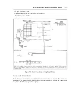
Self-supporting frames usually are bolted directly to the base floor (see figure 7-18, Floor-Secured
Frame Installation); this method of installation requires the removal of the raised floor stringers, Obtain
the cooperation of the floor installer to install frames. Use a frame whose height has been increased to
fit the raised floor, and make sure you include the increased height when ordering them.
You also may install self-supporting frames by bolting them to the top of the stringer system. Before
planning this approach, confer with the customer and the manufacturer of the raised-floor system. Brace
all self-supporting frames at their tops whether you have anchored them to the base floor or to the top of
the stinger system.
Floor Plan
Consult with the National Engineering Center (NEC) to obtain a detailed floor plan for the system 85 of
DEFINITY Generic 2 installation. This includes cable distances, tile cutouts, the relationship of the
Generic 2 with universal modules equipment to the stringer system, and the relationship of the MDF to
the stinger system.
Содержание 9601
Страница 1: ...555 104 630 Issue 2 June 1991 DEFINITY Communications SystemGeneric 2 and System 85 Wiring ...
Страница 57: ...2 34 MDF IDF DESIGN SYSTEM 85 AND DEFINITY GENERIC 2 WITH TRADITIONAL MODULES ...
Страница 67: ...3 10 ELECTRICAL PROTECTION SYSTEM 85 AND DEFINITY GENERIC 2 WITH TRADITIONAL MODULES ...
Страница 73: ...4 6 PORT PACKS DCP REPEATERS SYSTEM 85 AND DEFINITY GENERIC 2 WITH TRADITIONAL MODULES ...
Страница 85: ...6 6 OVERVIEW DEFINITY GENERIC 2 WITH UNIVERSAL MODULES ...
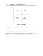
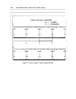
Страница 102: ...MDF lDF DESIGN DEFINITY GENERIC 2 WITH UNIVERSAL MODULES 7 17 Figure 7 8 Combined Trunk and Line Ports ...
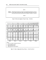
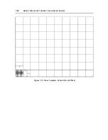
Страница 112: ...MDF lDF DESIGN DEFINITY GENERIC 2 WITH UNIVERSAL MODULES 7 27 Figure 7 16 Floor Template 24 Inch Tile L472367 ...
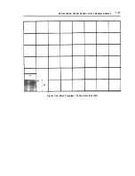
Страница 113: ...7 28 MDF lDF DESIGN DEFINITY GENERIC 2 WITH UNIVERSAL MODULES Figure 7 17 Floor Template Cabinet Lineup L472368 I I ...
Страница 115: ...7 30 MDF lDF DESIGN DEFINlTY GENERIC 2 WITH UNIVERSAL MODULES Figure 7 18 Floor Secured Frame Installation ...
Страница 119: ...7 34 MDF lDF DESIGN DEFINITY GENERIC 2 WITH UNIVERSAL MODULES ...
Страница 123: ...8 4 ELECTRICAL PROTECTION DEFINlTY GENERIC 2 WITH UNIVERSAL MODULES ...
Страница 135: ...10 8 INSTALLATION EXAMPLE DEFINITY GENERIC 2 WITH UNIVERSAL MODULES ...
Страница 139: ...11 4 BRI DEFINITY GENERIC 2 WITH UNIVERSAL MODULES ...
Страница 174: ...GL 12 GLOSSARY ...