Avaya 9601 Скачать руководство пользователя страница 65

3-8

ELECTRICAL PROTECTION: SYSTEM 85 AND DEFINITY GENERIC 2 WITH TRADITIONAL MODULES

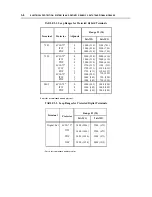
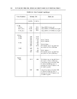
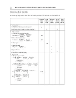
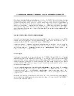
TABLE 3-1. Loop Ranges for Protected Hybrid Terminals

Terminal

7203

 7205

MET

Protector

Adjuncts

4C3S-75*

ITW
PDP

4C3S-75*

ITW
PDP

4C3S-75*

ITW
PDP

4C3S-75*

ITW
PDP

4C3S-75*

ITW

PDP

0
0
0

0
0
0

1
1
1
2
2
2

0
0
0

Range Ft (M)

24AWG

3000 (914)
3000 (914)

3000 (914)

3000 (914)
3000 (914)
3000 (914)

1750 (533)
1750 (533)
1750 (533)
1000 (305)
1000 (305)

1000 (305)

1000 (305)
1000 (305)
1000 (305)

26AWG

2300 (701 )
2300 (701)
2300 (701)

2000 (610)
2000 (610)
2000 (610)

1100 (335)
1100 (335)
1100 (335)

750 (229)
750 (229)
750 (229)

1000 (305)
1000 (305)
1000 (305)

*This is the recommended module protector.

TABLE 3-2. Loop Ranges for Protected Digital Terminals

Range Ft (M)

Terminal

Protector

24AWG

26AWG

Digital Set

4C3S-75*

3400 (1036)

2200 (671)

ITW

3400 (1036)

2200 (671)

PDP

3400 (1036)

2200 (671)

DLP

5000 (1524)

4000 (1219)

*This is the recommended module protector.

Содержание 9601

Страница 1: ...555 104 630 Issue 2 June 1991 DEFINITY Communications SystemGeneric 2 and System 85 Wiring ...

Страница 2: ...h case the user at his her own expense will be required to take whatever measures may be required to correct the interference Security In rare instances unauthorized individuals make connections to the telecommunications network through the use of remote access features in such event applicable tariffs require that the customer pay all network charges for traffic AT T cannot be responsible for suc...

Страница 3: ...OR SYSTEM 85 AND DEFINITY GENERIC 2 WITH TRADITIONAL MODULES SYSTEM ADJUCTS CROSS CONNECT FIELDS TERMINALS AND TERMINAL ADJUNCTS CONNECTIVITY GENERIC 2 WITH TRADITIONAL MODULE 2 MDF IDF DESIGN SYSTEM 85 AND DEFINITY GENERIC 2 WITH TRADITIONAL MODULES RECOMMENDED TERMINAL BLOCKS RECOMMENDED FRAMES FOR TERMINAL BLOCKS DESIGNING THE MDF DESIGNING THE MDF FOR A RAISED FLOOR RECOMMENDATION FOR IDF DESI...

Страница 4: ...KS DCP REPEATERS SYSTEM 85 AND DEFINITY GENERIC 2 WITH TRADITIONAL MODULES PORT CIRCUIT PACKS DCP REPEATERS 5 INSTALLATION EXAMPLE SYSTEM 85 AND DEFINITY GENERIC 2 WITH TRADITIONAL MODULES SIZING THE MDF CONSTRUCTING THE MDF 6 OVERVIEW DEFINITY GENERIC 2 WITH UNIVERSAL MODULES MAJOR COMPONENTS MULTICARRIER MODULE SYSTEM ADJUNCTS CROSS CONNECT FIELDS TERMINALS AND TERMINAL ADJUNCTS CONNECTIVITY MAJ...

Страница 5: ... DEFINITY GENERIC 2 WITH UNIVERSAL MODULES RECOMMENDED PROTECTORS PROTECTION MATRIX 9 PORT PACKS DEFINITY GENERIC 2 WITH UNIVERSAL MODULES PORT CIRCUIT PACKS DCP REPEATERS 10 INSTALLATION EXAMPLE DEFINITY GENERIC 2 WITH UNIVERSAL MODULES SIZING THE MDF CONSTRCUTING THE MDF 11 BRI DEFINITY GENERIC 2 WITH UNIVERSAL MODULES BRI TERMINALS BRI POWER SUPPLIES 12 ADJUNCT POWER SUPPLIES INDIVIDUAL POWER S...

Страница 6: ...vi CONTENTS 13 FIBER OPTICS 13 1 LCTT 13 1 CONNECTORS 13 1 PADDLEBOARD RANGE LIMITATIONS 13 1 14 INSERT LABELS GLOSSARY 14 1 GL 1 INDEX IN 1 ...

Страница 7: ... Floor Template 18 Inch Tile L472366 Figure 2 15 Floor Template 24 Inch Tile L472367 Figure 2 16 Floor Template Cabinet Lineup L472368 Figure 2 17 Floor Secured Frame Installation Figure 2 18 Example of Label Filled In Figure 3 1 Placement of Electrical Protectors on CO Side of Switch Figure 5 1 7 Module System Wall Mounted on Type 1 Frame Figure 5 2 7 Module System Mounted on Self Supporting Type...

Страница 8: ... 24 Inch Tile L472367 Floor Template Cabinet Lineup L472368 Floor Secured Frame Installation Example of Label Filled In 7 Module System Wall Mounted on Type 1 Frames 7 Module System Wall Mounted on Type 2 Frames 7 Module System Mounted on Self Supporting Type 1 Frame Front 7 Module System Mounted on Self Supporting Type 1 Frame Rear 7 Module System Mounted on Self Supporting Type 2 Frame From 7 Mo...

Страница 9: ...CONTENTS ix Figure 14 12 Insert Labels Partial Reproductions 14 16 Figure 14 13 Insert Labels Partial Reproductions 14 17 Figure 14 14 Insert Labels Partial Reproductions 14 18 ...

Страница 10: ... Modules Protection Matrix Port Circuit Pack Cabling Terminals and Peripherals Served by Port Circuit Packs Voice Terminal Loop Ranges 300 Pair Terminal Blocks 100 Pair Terminal Blocks 2 2 2 2 2 8 2 14 2 18 2 20 3 8 3 8 3 9 4 2 Type 1 Frame Ordering Information Type 2 Frame Ordering Information Mounting Methods Module Allocation per Zone with Type 1 Frame Module Allocation per Zone with Type 2 Fra...

Страница 11: ...vered in the Premises Distribution System Design Guide are not covered in this document Information outlets IO at the workstations Horizontal subsystem installation cable Riser subsystem distribution cable Campus subsystem distribution cable INTENDED AUDIENCES This document is intended primarily for the premises services consultant PSC who is charged with designing an MDF and IDF for a System 85 o...

Страница 12: ...QUISITE SKILLS AND KNOWLEDGE This document assumes that you are familiar with the PDS installation guidelines and hardware If you are not read the Premises Distribution System Design Guide 555 400 602 before you read this document ...

Страница 13: ...ule system 85 or DEFINITY Generic 2 with traditional modules Chapter 6 Overview DEFINITY Generic 2 with Universal Modules A guide to the major differences and important features of DEFINITY Generic 2 with universal modules that are not available in System 85 and DEFINITY Generic 2 with traditional modules Chapter 7 MDF IDF Design DEFINITY Generic 2 with Universal Modules Designing the MDF and IDF ...

Страница 14: ...ocument for readers who are familiar with distribution systems and the hardware and cabling necessary for their construction Provides step by step instruction in designing a PDS for a building or a campus of buildings even when the specific voice or data systems are not known plus information on specific PDS components and methods Not intended as a tutorial in PDS NOTE The Premises Distibution Sys...

Страница 15: ...ties network features and configurations available methods for managing the system and AT T s support for planning and installation for training and for maintenance An Introduction to DEFINITY Communications System Generic 2 555 104 020 A general description for prospective customers account teams and others who need an overview of DEFINITY Generic 2 Includes information based on desktop system ne...

Страница 16: ...we have tried to make this document fit your needs we are interested in your suggestions for improving it and urge you to fill one out If the reader comment cards have been removed from this document please send your comments to AT T Technical Publications Department Room 22 2C11 11900 North Pecos Street Denver Colorado 80234 ...

Страница 17: ...s of System 85 and DEFINITY Generic 2 with traditional modules that are major factors in the design of a wiring installation For more comprehensive information on System 85 see the System 85 System Description Reference Manual 555 103 201 For more details on DEFINITY Generic 2s with traditional modules see the DEFINITY Communications System Generic 2 and System 85 System Description Reference Manu...

Страница 18: ...locations can be connected to the central switch by a digital service level 1 DS1 link that uses remote group interface RGI circuit packs as the DS1 interfaces The RGI circuit packs are installed in the DSl MFAT carrier of the central module and in the remote group housing RGH at the remote location The maximum distance that a remote group can be located from the central module is 100 mi over T1 l...

Страница 19: ...emos using just the telephone The AUDIX processor uses disk storage for the encoded voice messages When AUDIX is operating with a System 85 or DEFINITY Generic 2 with traditional modules it connects to the data communications interface unit DCIU of the switch through synchronous control channels for data transmission and to analog ports for voice transmission Several PBXs can share one AUDIX adjun...

Страница 20: ...ntities that are dictated by the overall wiring design TERMINALS AND TERMINAL ADJUNCTS A variety of terminals and terminal adjuncts connect to the System 85 and DEFINITY Generic 2 with traditional modules When you are designing the wiring installation according to the basic or enhanced premises distribution system PDS guidelines the types of terminals and peripherals being installed at the worksta...

Страница 21: ...e line port circuit for the desired workstation The path exits the switch from the line port circuit and proceeds along a cable from the backplane to the section of the purple field for lines on the MDF The purple field is cross connected to the white field the distribution field of the MDF The path leaves the white field via a distribution cable that connects to the white field of the IDF The cir...

Страница 22: ...1 6 OVERVIEW SYSTEM 85 AND DEFINITY GENERIC 2 WITH TRADITIONAL MODULES I I Figure 1 1 System 85 and DEFINITY Generic 2 with Traditional Module Connectivity ...

Страница 23: ...ape system DTS and DEFINITY Manager II a maintenance and administration system DEFINITY Generic 2 functions with both the traditional and universal modules DEFINITY Generic 2 system cabinets and the universal module are described in more detail in chapter 6 Overview DEFINITY Generic 2 with Universal Modules The traditional module uses DEFINITY Generic 2 system cabinets and System 85 port board tec...

Страница 24: ...ed The 110A comes in several models that are called terminal blocks Each terminal block is composed of a wiring block and a unique combination of connecting blocks A wiring block is where the equipment distribution or central office CO cables terminate The connecting block which snaps onto the front of the wiring block is where the jumper wires are attached to establish a path from the pairs in on...

Страница 25: ...Pair Terminal Blocks Product Code Comcode Height in ll0AB1 l00FT 110AB1 100CT ll0AB1 l00CTM ll0AB1 l00CB ll0AB1 l00CBM 103823845 3 59 104408992 13 29 104409008 13 29 104408026 13 29 104408075 13 29 NOTE The meanings for the alphabetic suffixes to the model codes are as follows Field Terminated Connectorized w female connector Connectorized w male Connectorized bottom w female connector Connectoriz...

Страница 26: ... a column for either frame or wall mounted installations See figure 2 1 Maximum Column 1500 Pairs Five 300 Pair Terminal BIocks Higher columns are hard to reach and make connecting and disconnecting jumper wires difficult Also if horizontal space is limited you can use 1800 pair columns for small installations keeping in mind that this height could present problems a Figure 2 1 Maximum Column 1500...

Страница 27: ... by using a spudger tool 110 tool comcode 405423260 Do this by Removing jumpers with a perpendicular motion from the ccnnecting block Always using the spudger to clean the contacts immediately after you remove the jumper wires Jumper Placement Rules H1 EXAMPLE 1 H2 EXAMPLE 2 EXAMPLE 3 Index Strips consist of a right and a left half Dress pairs l to 12 to the left and dress pairs 13 to 25 to the ri...

Страница 28: ...nector panels for equipment rooms with high ceilings or for equipment rooms with raised floors You also can order frames fitted with mountings to hold protector units Whenever possible use the XLBET frames either self supported or wall mounted for the MDF The benefits and advantages for both the customer and AT T of easier ordering better aesthetics and easier connecting and disconnecting of jumpe...

Страница 29: ... Frames with 18 000 Pair Capacity Type 2 Frame The type 2 frame shown in figure 2 4 Seven Type 2 Frames with 16 800 Pair Capacity is a special frame with added jumper capacity You can terminate 2400 pairs on each of its sides Cross connections on the type 2 can be made either from top to bottom or from side to side depending on the size and shape of the installation Use the type 2 frame for large ...

Страница 30: ... 2 WITH TRADITIONAL MODULES 2 7 LEGEND G GREEN NETWORK FIELD Y YELLOW AUXILIARY AND MISCELLANEOUS FIELD W WHITE DISTRIBUTION FIELD P PURPLE EQUIPMENT FIELD S SPARE WITH CROSS CONNECT BLOCKS Figure 2 4 Seven Type 2 Frames with 16 800 Pair Capacity ...

Страница 31: ...ng to table 2 3 Type 1 Frame Ordering lnformation ordering information for the type 2 frame is in table 7 4 Type 2 Frame Ordering Information TABLE 2 3 Type 1 Frame Ordering Information Comcode Top Bottom Remarks 105 367 692 1200 pair 1800 pair field Single sided connectorized terminated with 110C 4 Specify the blocks block type 105 367 718 2400 pair 3600 pair field Double sided connectorized tcrm...

Страница 32: ...uipment room be sure that your completed design for the MDF is compatible with your equipment room plans or with the room that you have selected for the MDF location When designing the MDF for a raised floor installation follow the instructions under Designing the MDF for a Raised Floor in this chapter Figure 2 5 Overall Equipment Wiring Plan shows the overall equipment wiring plan for R2V1 throug...

Страница 33: ...2 10 MDF lDF DESIGN SYSTEM 85 AND DEFINITY GENERIC 2 WITH TRADITIONAL MODULES COMMUNICATIONS Figure 2 5 Overall Equipment Wiring Plan ...

Страница 34: ...standard electrical protection that the telephone company provides The total number of pairs in the network services cable is governed by the number of pairs that the customer needs to connect to the network It is also governed by the number of pairs that the telephone company supplies For example if the customer needs to connect 750 pairs to the network and the telephone company supplies a 900 pa...

Страница 35: ...e labels is where all of the distribution cables terminate Distribution cables are the cables that run from the MDF in the equipment room to the IDF in the closets They are sometimes called house backbone riser campus or black cables This document calls them distribution cables The Premises Distribution System Design Guide 555 400 602 presents several approaches to sizing the distribution cables b...

Страница 36: ... converted them to the number of 300 pair blocks needed decide the following Where to locate the MDF How to mount the terminal blocks How to arrange the terminal blocks How to connect to the terminal blocks Locating the MDF Locate MDF as close to the switch cabinets as possible The preferred location is in the equipment room but if space is not available locate it in a separate area within 20 to 3...

Страница 37: ... the terminal blocks with the following factors in mind Cable terminations to the fields and how the fields cross connect The type of port fields and the necessity for short jumper lengths Possible zone configurations These factors are discussed in the sections that follow Cable Terminations and Cross Connections Terminate the equipment port cables close to the distribution cables as suggested in ...

Страница 38: ...ths For most installations combine the line and trunk fields to accommodate the universal port carrier as shown in figure 2 7 Combined Trunk and Line Ports Use the arrangement in figure 2 8 Separated Trunk and Line Ports if you are using 110P cross connect hardware in the installation or if managing jumper wires becomes difficult due to a large number of analog trunks cross connected between the g...

Страница 39: ...2 16 MDF lDF DESIGN SYSTEM 85 AND DEFINITY GENERIC 2 WITH TRADITIONAL MODULES Figure 2 7 Combined Trunk and Line Ports ...

Страница 40: ...p Second the necessity to make cross connections between the ends of the frame lineup can cause an overflow of jumper wires in the troughs of the middle frames To avoid these problems divide frame lineups into zones if they exceed 16 ft and terminate more than 5 modules A zone is a section of the MDF with a maximum horizontal distance of 16 ft Cross connections can be made only between the cables ...

Страница 41: ...Zone with Type 1 Frame shows the number of modules allocated per zone when you design an MDF with a type 1 frame Each type 1 frame can accommodate 3000 jumper pairs per side Figure 2 9 Zone Arrangement of Type 1 Frame Plan View and figure 2 10 Zone Arrangement of Type 1 Frame Front View Zone 2 show a type 1 frame used in a zone arrangement TABLE 2 5 Module Allocation per Zone with Type 1 Frame Num...

Страница 42: ...MDF lDF DESIGN SYSTEM 85 AND DEFINITY GENERIC 2 WITH TRADITIONAL MODULES 2 19 Figure 2 9 Zone Arrangement of Type 1 Frame Plan View Figure 2 10 Zone Arrangement of Type 1 Frame Front View Zone 2 ...

Страница 43: ...er zone when you design an MDF with a type 2 frame Each type 2 frame can accommodate 4000 jumper pairs per side Figure 2 11 Zone Arrangement of Type 2 Frame Plan View and figure 2 12 Zone Arrangement of Type 2 Frame Front View Zone 2 show a type 2 frame used in a zone arrangement TABLE 2 6 Module Allocation per Zone with Type 2 Frame Number of Number of Number of Modules zones Modules for Zone 1 8...

Страница 44: ...MODULES 2 21 Figure 2 11 Zone Arrangement of Type 2 Frame Plan View LEGEND Y YELLOW AUXILIARY AND MISCELLANEOUS FIELD W WHITE DISTRIBUTION FIELD P PURPLE EQUIPMENT FIELD S SPARE WITH CROSS CONNECT BLOCKS Figure 2 12 Zone Arrangement of Type 2 Frame Front View Zone 2 ...

Страница 45: ...pairs at one zone and 200 pairs at the other Do not add extra cable pairs to a distribution cable to achieve an equal number of terminations at all zones That is do not add 100 pairs to the 300 pair cable in order to terminate 200 pairs at both zones Do not spread the equipment ports at the MDF When you use zones in the equipment room the proper cross connections at the IDF are crucial Figure 2 13...

Страница 46: ... Figure 2 13 Closet Cross Connects Using Type 1 Frames Connecting to Terminal Blocks The 110A and 110P cross connect hardware are available with connectors or without connectors for field termination of cables The determination of whether to use cross connect hardware with or without connectors is best made at the site but in general the following guidelines apply Use cross connect hardware withou...

Страница 47: ...ther equipment Spare field Convert spare field space to a yellow field dedicated to the clock Custom installation As a last resort install a 110A 300 block dedicated to the clock on or near the MDF DESIGNING THE MDF FOR A RAISED FLOOR A modern communications system is perceived by the customer to look like a computer installation For this reason some customers request that the communications syste...

Страница 48: ... use ducts for such cables as the input output I O cables which connect the switch to the MDF Space availability under the floor There should be adequate space for ducts and cables to be installed and what is under the raised floor for example electrical conduits air conditioning ducts water pipes Modification of the floor tiles Cutouts in floor tiles will have to be made to accommodate the MDF Di...

Страница 49: ...2 26 MDF lDF DESIGN SYSTEM 85 AND DEFINITY GENERIC 2 WITH TRADITIONAL MODULES 18 Figure 2 14 Floor Template 18 Inch Tile L472366 ...

Страница 50: ...2 27 MDF lDF DESIGN SYSTEM 85 AND DEFINITY GENERIC 2 WITH TRADITIONAL MODULES 24 2 ˆ 24 v Figure 2 15 Floor Template 24 Inch Tile L472367 ...

Страница 51: ...2 28 MDF lDF DESIGN SYSTEM 85 AND DEFINlTY GENERIC 2 WITH TRADITIONAL MODULES Figure 2 16 Floor Template Cabinet Lineup L472368 ...

Страница 52: ...directly that is without frames Self supporting frames usually are bolted directly to the base floor figure 2 17 Floor Secured Frame Installation and this method of installation requires the removal of the raised floor stringers Obtain the cooperation of the floor installer to install frames Use a frame whose height has been increased to fit the raised floor and make sure you include the increased...

Страница 53: ...2 30 MDF lDF DESIGN SYSTEM 85 AND DEFINITY GENERIC 2 WITH TRADITIONAL MODULES NOTE Connector brackets can be placed on the floor for easy connecting Figure 2 17 Floor Secured Frame Installation ...

Страница 54: ...ution System Design Guide 555 400 602 and in the AT T System 75 Wiring 555 200 111 document Mounting the Terminal Blocks If you are terminating fewer than 1200 cable pairs riser and installation cables combined on an IDF wall mount the terminal blocks directly without a frame If you are terminating more than 1200 pairs on an IDF use a wall mounted type 1 frame discussed under Recommended Frames fo...

Страница 55: ...r coding of the labels is also used to set off specific fields on the MDF and IDFs as follows On the MDF Green for the network services CO trunks field Yellow for the auxiliary field Purple for the equipment ports field White for the building distribution field cables coming from the IDFs Blue for the installation field On the IDFs White for the building distribution field cables coming from the M...

Страница 56: ...as 123 4567 Select code of sheets needed upper righthand corner of each sheet Number of sheets needed A partial reproduction of each label sheet is shown in chapter 14 Insert Labels CUSTOMER PARTICIPATION Customer partcipation in wiring administration allows the customer to set up tear down and alter cross connections on the building distribution field of the MDF and on the IDFs Because 110A cross...

Страница 57: ...2 34 MDF IDF DESIGN SYSTEM 85 AND DEFINITY GENERIC 2 WITH TRADITIONAL MODULES ...

Страница 58: ...ge surge by striking on or near the distribution cables Power lines that fall across the distribution cables are a power cross which also causes a high voltage surge Power lines that run long distances parallel and close to telephone lines create power induction And an increase in the voltage at the grounding point because of a power fault or because of lightning current flowing into the ground in...

Страница 59: ...e equipped with single point ground lightning protection to prevent lightning induced surges from traveling through the power system Single point grounding provides for all grounds in the communications system to originate from a single point or node on the AC protector cabinet If lightning strikes the communications system avoids damage because it rises and falls in potential with the single poin...

Страница 60: ...n they require both overvoltage and sneak current protection The telephone company installs primary overvoltage protection in its BEFs for its cables from the central office CO when it has determined that those cables are exposed it does not install sneak current protection Determine whether or not their primary protection adequately safeguards AT T s cables and equipment and if it does not add th...

Страница 61: ...rical voltage surge to arc through the gas to ground On average gas tubes operate when a voltage of about 300V occurs Use gas tubes to protect against surges caused by lightning power crosses power induction and ground potential rise Solid State Devices A solid state device uses a semiconductor in one of two ways to protect against high voltage surges It either shunts the high voltage to ground or...

Страница 62: ...s additional protection for equipment with a specific vulnerability A DLP is an isolation transformer that provides protection for digital terminals by isolating the low impedance phantom powered circuit from an exposed loop Local power must be provided if the digital terminals are to be port powered RECOMMENDED PROTECTORS Following are recommended electrical protectors that can be used for primar...

Страница 63: ...ls ITW Linx LP2 100 068 comcode 405077355 PEC 65541 and 65541A an avalanche diode gas tube sneak current fuse protector unit This protector unit has the same loop range for terminals as a PDP protector see table 3 1 Loop Ranges for Protected Hybrid Terminals and table 3 2 Loop Ranges for Protected Digital Terminals and is recommended for the protection of small numbers of cabling pairs up to 50 pa...

Страница 64: ...58 PEC 24900 single circuit protector contained in a wall mounted 104A connector block housing DLPs are used to protect 7400 series digital terminals and SN270B circuit packs and must be installed with a primary protector DLPs are especially recommended for protection against lightning and must be installed at both ends of the exposed cable serving an SN270B or a digital terminal Terminals protect...

Страница 65: ... 3000 914 3000 914 3000 914 1750 533 1750 533 1750 533 1000 305 1000 305 1000 305 1000 305 1000 305 1000 305 26AWG 2300 701 2300 701 2300 701 2000 610 2000 610 2000 610 1100 335 1100 335 1100 335 750 229 750 229 750 229 1000 305 1000 305 1000 305 This is the recommended module protector TABLE 3 2 Loop Ranges for Protected Digital Terminals Range Ft M Terminal Protector 24AWG 26AWG Digital Set 4C3S...

Страница 66: ...hannel service units CSU as the network interface NI If the NI is provided then primary protection is provided between the NI and network facilities Gas tube protectors are recommended Circuit pack not approved for exposed applications Analog line circuit packs require primary protection The SN233C must be protected by console repeaters and primary protection when used for exposed console service ...

Страница 67: ...3 10 ELECTRICAL PROTECTION SYSTEM 85 AND DEFINITY GENERIC 2 WITH TRADITIONAL MODULES ...

Страница 68: ...s one 25 pair cable for each slot The table also gives the number of ports for each circuit pack There are four ports for each digital pack and eight ports for each analog pack If you receive just circuit pack information types and quantities from the Marketing Branch Organization MBO but no information on the cabling accompanying those packs use table 4 1 Port Circuit Pack Cabling to calculate th...

Страница 69: ...228 Off premises station line 8 trunk aux bldg dist 2 SN229 On premises station line 8 2 bldg dist SN224 MFET line port 4 2 SN230 CO trunk 4 SN231 Auxiliary trunk 4 SN232 DID trunk 4 SN233 Tie trunk 4 SN238 EIA 4 trunk aux 2 trunk aux 2 trunk aux 2 2 trunk aux 2 trunk aux bldg dist SN241 Contact interface 4 2 bldg dist 2 bldg dist 2 bldg dist 2 SN242 Automatic number ID 1 SN243 Data port 4 SN270 D...

Страница 70: ...N17B MFAT SN228 Off premises station line 2500 7101A 7103A SN229 On premises station line 2500 7101A 7103A SN224 MFET line port SN233 Tie trunk attendant console SN238 EIA SN243 Data port SN270 Digital voice data port Discontinued Term Periph Served 7303S 7305S 7203H 7205H Attendant console RS232 terminals Analog modems modem pooling 7401D 7404D 7405D 7406D 7407D 510D 515 ...

Страница 71: ...00 With 1 module 1150 750 With 2 modules 7303S 1540 1000 1000 650 With 1 adjunct 3075 2000 With adjunct power supplied from the closet or at the workstation 7305S 1000 650 690 450 With 1 adjunct 3075 2000 With adjunct power supplied from the closet or at the workstation Digital 740X 5230 3400 With adjunct power supplied from the closet or at the workstation Loop range can be extended 5000 ft with ...

Страница 72: ... that has 110 VAC power If a repeater is exposed to electrical hazards install primary protection before it Ensure that the circuit breaker to the 110 VAC power for the repeaters is labeled with a notice cautioning personnel not to disrupt power to the repeaters However the repeaters do contain a reserve battery that permits them to operate for about two hours after AC power has been shut off or d...

Страница 73: ...4 6 PORT PACKS DCP REPEATERS SYSTEM 85 AND DEFINITY GENERIC 2 WITH TRADITIONAL MODULES ...

Страница 74: ... have to be terminated on this field which eliminates the need for terminal blocks The auxiliary and miscellaneous field which uses yellow labels is where the cables from the auxiliary equipment terminate Two auxiliary cabinets whose contents are unknown serve this system Allow for the termination of twelve 25 pair cables from each cabinet In addition a maximum of twelve 25 pair cables from the co...

Страница 75: ... 0 2 Yellow Field A Auxiliary cabinet terminations 2 cabinets x 12 cables 25 pairs x 600 cabinet cable B CC cabinet termination 1 cabinet x 12 cables x 25 pairs 300 cabinet cable C Total pairs 900 D Blocks needed 900 pairs 300 pairs 3 block E Spare blocks 1 F Number of required blocks 2 4 3 Purple Field A Sizing largest module 9 step carriers 8 cables x 25 pairs i x module carrier cable 1800 pairs...

Страница 76: ... frames needed despite the block count Location of the MDF The size of the equipment room governs the location of the MDF For this installation the 25 ft wide wall space is available close enough to the equipment to permit the use of either wall mounted or self supporting frames Terminal block mounting For an installation of this size the terminal blocks can only be mounted on frames Choose which ...

Страница 77: ...special frames since each spans three of the type 1 frames Also the yellow field shares the same frame as module 1 Third these layouts require jumpers longer than the recommended 16 ft Self supporting frames Mounting the terminal blocks on self supporting frames which is preferable to wall mounting for this installation requires five type 1 frames or seven type 2 frames The type 1 frame arrangemen...

Страница 78: ...the distribution cable is separated on the MDF One side of the frame lineup supports four modules and the other side supports only three thus most of the placed on the side with three modules Figure 5 4 7 Module System Mounted on Self Supporting Type 2 Module System Mounted on Self Supporting Type 2 Frame Rear spare distribution cable pairs are Frame Front and figure 5 5 7 show the same arrangemen...

Страница 79: ...Mounted on Self Supporting Type 2 Frame Front Figure 5 5 7 Module System Mounted on Self Supporting Type 2 Frame Rear Cable connections to the MDF In this example all connections to the frames from the equipment are by connector cables All distribution cables are field terminated directly to the terminal blocks ...

Страница 80: ...cations switching modules with each module providing as many as 1440 ports for a universal module The multimodule architecture uses a time multiplexed switch TMS as the link between communications switching modules Cabinet Types The Generic 2 system has three types of cabinets the CC TMS TMS and UMC The CC carrier J58888AB and TMS carrier J58888C are housed in the new CC TMS cabinet together both ...

Страница 81: ...INITY Generic 2 with traditional modules The CPC introduces a major improvement in cabling between the switch and wall fields with the new I O connector plate on the rear of the UMC cabinet The I O connector plate provides 20 25 pair connectors to interface circuit pack slots to the cross connect field The cables for these connections are B25A male to female M F connectors replacing the male to ma...

Страница 82: ...plication functions that do not reside on the switch lncluded among these are Audio Information Exchange AUDIX 3B2 3B5 and Adjunct Processor 16 APl6 AUDIX The AUDIX system is compatible with all versions of System 85 and DEFINITY Generic 2 More detailed descriptions of AUDIX appear in the AUDIX Reference Manual 585 300 201 APs APs are compatible with R2V4 and DEFINITY Generic 2 with either traditi...

Страница 83: ...EFINITY Generic 2 with universal modules is similar to that of System 85 and DEFINITY Generic 2 with traditional modules A major difference is the use of unshielded M F B25A cables to connect the switch to the male connectorized cross connect field wherever possible Previously installed systems may require M M A25D connectorized cables See figure 1 1 System 85 and DEFINITY Generic 2 with Tradition...

Страница 84: ...t contains the hardware that allows the CC to interrogate and scan the ports send instructions to them and create transmission path connections The SCMCC uses existing module control circuit packs and acts as an intelligent interface between the CC and the ports At least one SCMCC is required for each SCM SCPC J58890H The SCPC supports the port network complex of the SCMCC stack The cabinet uses e...

Страница 85: ...6 6 OVERVIEW DEFINITY GENERIC 2 WITH UNIVERSAL MODULES ...

Страница 86: ...f a wiring block and a unique combination of connecting blocks A wiring block is where the equipment distribution or central office CO cables terminate The connecting block which snaps onto the front of the wiring block is where the jumper wires are attached to establish a path from the pairs in one cable to the pairs in another cable In order to simplify the design of wiring installations only tw...

Страница 87: ... 3 59 ll0AB1 100CT 104408992 13 29 ll0AB1 100CTM 104409008 13 29 ll0ABl 100CB 104408026 13 29 ll0AB1 100CBM 104408075 13 29 NOTE The meanings for the alphabetic suffixes to the model codes are as follows Field terminated Connectorized w female connector Connectorized w male Connectorized bottom w female connector Connectorized bottom w male When you are enlarging an existing IDF or MDF constructed...

Страница 88: ...rame or wall mounted installations See figure 7 1 Maximum Column 1500 Pairs Five 300 Pair Teminal Blocks Taller columns are hard to reach and make connecting and disconnecting jumper wires difficult Also if horizontal space is limited you may use 1800 pair columns for small installations as long as height does not present problems A WALL MOUNTED COLUMN B FRAME MOUNTED COLUMN Figure 7 1 Maximum Col...

Страница 89: ...inal blocks by using a spudger tool 110 tool comcode 405423260 Clean contacts by Removing jumpers with a perpendicular motion from the connecting block Always using the spudger to clean the contacts immediately after you remove the jumper wires Jumper Placement Rules Index strips consist of a right and a left half Dress pairs l to 12 to the left and dress pairs 13 to 25 to the right Eliminate spid...

Страница 90: ...can order AT T frames in special heights to accommodate connector panels equipment rooms with high ceilings or equipment rooms with raised floors Also you can order frames fitted with mountings for protector units Whenever possible use the XLBET frames either self supported or wall mounted for the MDF The benefits and advantages for both the customer and AT T of easier ordering better aesthetics a...

Страница 91: ... 4 Seven Type 2 Frames with 16 800 Pair Capacity has added jumper capacity You may terminate 2400 pairs on each of its sides Cross connections on the type 2 frame can be made either from top to bottom or from side to side depending on the size and shape of the installation Use the type 2 frame for large installations that require more than nine frames in a lineup ...

Страница 92: ...MDF lDF DESIGN DEFINITY GENERIC 2 WITH UNIVERSAL MODULES 7 7 Figure 7 4 Seven Type 2 Frames with 16 800 Pair Capacity ...

Страница 93: ...mation and table 7 4 Type 2 Frame Odering Information TABLE 7 3 Type 1 Frame Ordering Information Comcode Top Bottom Remarks 105 639 561 1200 pair 1800 pair field Single sided connectorized f i e l d with male terminated t o p s 105 639 538 2400 pair 3600 pair field Double sided connectorized f i e l d with male terminated t o p s 105 174 148 6 0 0 p a i r Kit for the connectorization above frames...

Страница 94: ...st solution in terms of both function and cost Since the design of the MDF affects the design of the equipment room be sure that your completed design for the MDF is compatible with your equipment room plans or with the room that you have selected for the MDF location When designing the MDF for a raised floor installation follow the instructions under Designing the MDF for a Raised Floor in this c...

Страница 95: ...7 10 MDF lDF DESIGN DEFINITY GENERIC 2 WITH UNIVERSAL MODULES Figure 7 5 Overall Equipment Wiring Plan DEFINITY Generic 2 with Universal Modules ...

Страница 96: ...ectrical protection that the telephone company provides The total number of pairs in the network services cable is governed by the number of pairs that the customer needs to connect to the network It is also governed by the number of pairs that the telephone company supplies For example if the customer needs to connect 750 pairs to the network and the telephone company supplies a 900 pair cable th...

Страница 97: ...ol UMC cabinet containing space for three CPCs J58890BB therefore space must be provided to serve all three carriers whether they are used or not Allow for the termination of 1800 pairs for the port field Increase or decrease the number in 300 pair increments according to actual needs NOTE Use the same rules for designing single carrier port cabinet SCPC installations but note that there will be e...

Страница 98: ...tation is allotted a minimum of two cable pairs Allow the 25th pair in each 25 pair bundle to serve as a spare Allot three cable pairs for each workstation if the customer requests single point administration It is recommended that you terminate large numbers of spare pairs requested by the customer on a specially designated area of the MDF This guideline is recommended for efficiency since the sp...

Страница 99: ...irs For example to terminate 75 4 pair DIW cables you would use two blocks instead of one Constructing the MDF Once you have calculated the number of cable pairs needed for each of the MDF areas and converted them to the number of 300 pair blocks needed decide the following Where to locate the MDF How to mount the terminal blocks How to arrange the terminal blocks How to connect to the terminal bl...

Страница 100: ... the terminal blocks for installations of all module sizes is desirable but those of 9 modules or more must be frame mounted Arranging the Terminal Blocks Arrange the terminal blocks with the following factors in mind Cable terminations to the fields and how the fields cross connect The type of port fields and the necessity for short jumper lengths Possible zone configurations These factors are di...

Страница 101: ...ed on the MDF other than Generic 2 with universal modules are terminated on the MDF add two more fields to the arrangement Port Fields and Short Jumper Lengths For most installations combine the line and trunk fields to accommodate the CPC as shown in figure 7 8 Combined Trunk and Line Ports Some fields may be better arranged with separated port and trunk blocks as shown in figure 7 9 Separated Tr...

Страница 102: ...MDF lDF DESIGN DEFINITY GENERIC 2 WITH UNIVERSAL MODULES 7 17 Figure 7 8 Combined Trunk and Line Ports ...

Страница 103: ...per wires in the wireways of the middle frames To avoid these problems frame lineups that exceed 16 ft and terminate more than eight modules are divided into zones A zone is a section of the MDF that has a maximum horizontal distance of 16 ft Cross connections can be made only between the cables that terminate within the same zone This keeps the jumper wires short and easily manageable When the MD...

Страница 104: ...allocated per zone when you design an MDF with a type 1 frame Each type 1 frame can accommodate 3000 jumper pairs per side Figure 7 10 Zone Arrangement of Type 1 Frame Plan View and figure 7 11 Zone Arrangement of Type 1 Frame Front View Zone 2 show a type 1 frame used in a zone arrangement NOTE Type 1 frames are not recommended for greater than 10 modules TABLE 7 6 Module Allocation per Zone with...

Страница 105: ...RAME NUMBER ZONE 2 Figure 7 10 Zone Arrangement of Type 1 Frame Plan View LEGEND Y YELLOW AUXILIARY AND MISCELLANEOUS FIELD W WHITE DISTRIBUTION FIELD P PURPLE EQUIPMENT FIELD S SPARE WITH CROSS CONNECT BLOCKS Figure 7 11 Zone Arrangement of Type 1 Frame Front View Zone 2 ...

Страница 106: ... a 1 type 2 frame Each type 2 frame can accommodate 4000 jumper pairs per side Figure 7 12 Zone Arrangement of Type 2 Frame Plan View and figure 7 13 Zone Arrangement of Type 2 Frame Front View Zone 2 show a type 2 frame used in a zone arrangement TABLE 7 7 Module Allocation per Zone with Type 2 Frame Number of Number of Number of Modules Zones Modules for Zone 1 8 9 10 11 12 13 14 15 16 2 2 1 8 4...

Страница 107: ...air distribution cable You would terminate 100 pairs at one zone and 200 pairs at the other Do not add extra cable pairs to a distribution cable to achieve an equal number of terminations at all zones That is in the preceding rule you would not add 100 pairs to the 300 pair cable in order to terminate 200 pairs at both zones Do not spread the equipment ports at the MDF keep them in the same area W...

Страница 108: ... module 07 the cross connection in the closet goes to a pair in zone 2 Using this rule it is possible to keep the jumpers short at the equipment room cross connect field Figure 7 14 Closet Cross Connects Using Type 1 Frames Connecting to Terminal Blocks The 110A cross connect hardware is available with connectors or without connectors The determination of whether to use connectorized or field term...

Страница 109: ...llow portion of the wall field There are three ways to establish the yellow wall field cross connection In order of preference they are as follows Yellow field Use a portion of this field that has not been dedicated to other equipment Spare field Convert spare field space to a yellow field dedicated to the clock Custom installation As a last resort install a 110A 300 block dedicated to the clock o...

Страница 110: ...other hand if the local codes forbid the use of ordinary covering materials for the installation that you are planning use ducts for such cables as the input output I O cables which connect the switch to the MDF Space availability under the floor Is there adequate space for ducts and cables to be installed and what is under the raised floor for example electrical conduits air conditioning ducts wa...

Страница 111: ...7 26 MDF lDF DESIGN DEFINlTY GENERIC 2 WITH UNIVERSAL MODULES 18 2 ˆ 18 v Figure 7 15 Floor Template 18 Inch Tile L472366 ...

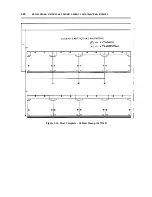
Страница 112: ...MDF lDF DESIGN DEFINITY GENERIC 2 WITH UNIVERSAL MODULES 7 27 Figure 7 16 Floor Template 24 Inch Tile L472367 ...

Страница 113: ...7 28 MDF lDF DESIGN DEFINITY GENERIC 2 WITH UNIVERSAL MODULES Figure 7 17 Floor Template Cabinet Lineup L472368 I I ...

Страница 114: ...s directly that is without frames Self supporting frames usually are bolted directly to the base floor see figure 7 18 Floor Secured Frame Installation this method of installation requires the removal of the raised floor stringers Obtain the cooperation of the floor installer to install frames Use a frame whose height has been increased to fit the raised floor and make sure you include the increas...

Страница 115: ...7 30 MDF lDF DESIGN DEFINlTY GENERIC 2 WITH UNIVERSAL MODULES Figure 7 18 Floor Secured Frame Installation ...

Страница 116: ...e recommendations in this section supplement the PDS guidelines and are essential to the design of IDFs Beyond these recommendations use your experience and best judgement in designing IDFs Recommended Terminal Blocks Use 110AB1 100 or 110AB1 300 terminal blocks for both the blue and white fields of the IDF Mounting the Terminal Blocks If you are terminating fewer than 1200 cable pairs riser and i...

Страница 117: ...also used to set off specific fields on the MDF and IDFs as follows O n t h e M D F Green for the network services CO trunks field Yellow for the auxiliary field Purple for the equipment ports field White for the building distribution field cables coming from the IDFs Blue for the installation field O n t h e I D F s White for the building distribution field cables coming from the MDF Blue for the...

Страница 118: ...567 Select code of sheets needed upper righthand corner of each sheet Number of sheets needed A partial reproduction of each label sheet is shown in chapter 14 Insert Labels CUSTOMER PARTICIPATION Customer participation in wiring administration allows the customer to set up tear down and alter cross connections on the building distribution field of the MDF and on the IDFs Because 110A cross connec...

Страница 119: ...7 34 MDF lDF DESIGN DEFINITY GENERIC 2 WITH UNIVERSAL MODULES ...

Страница 120: ...all provide protection in the standard analog voltage range of 220V to 300V and may include a heat coil for sneak current protection The 4C3S 75 enhanced primary protector is installed in place of the primary protector and operates at 75V The secondary protector is used in conjunction with primary protection and is installed on the equipment terminal or port side of the primary protector RECOMMEND...

Страница 121: ... mounting Secondary Protector Secondary protection for DEFINITY Generic 2 with universal modules is provided by the same data link protector DLP used in the System 85 and DEFINITY Generic 2 with traditional modules the DLP must be used in conjunction with primary protection DLPs used with 7400 sets are isolation transformers and require the terminal to be locally powered DLP is available in either...

Страница 122: ...l service unit CSU is provided then primary protection must be provided on the network side of the facilities The TN760C cannot be directly connected to exposed facilities The TN555 does not have tip and ring connections It connects directly to the TN767 via a special Y cable AT T 5 pin plug in protector units and primary protetectors that begin with the number 4 are equipped with heat coils that ...

Страница 123: ...8 4 ELECTRICAL PROTECTION DEFINlTY GENERIC 2 WITH UNIVERSAL MODULES ...

Страница 124: ...e housed in the universal module control UMC common port carrier CPC and the fields on the main distribution frames MDF where cables from those packs terminate There are 20 circuit packs per carrier and one 25 pair cable serves each pack The table also gives the number of ports for each circuit pack There are 8 ports for each digital pack and 8 or 16 ports for each analog pack Table 9 1 also lists...

Страница 125: ... 12 BLDG DIST 1 TN726 Data Line 8 BLDG DIST 1 TN735 MET Line 4 BLDG DIST 1 TN742 ONS Analog Line 8 BLDG DIST 1 or OFS Analog Line 8 Trunk AUX 1 TN746 Analog Line ONS 16 BLDG DIST 1 TN747B CO Trunk 8 Trunk AUX 1 TN753 DID Trunk 8 Trunk AUX 1 TN754 Digital Line 8 BLDG DIST 1 TN754B Digital Line 8 BLDG DIST 1 TN760C Tie Trunk Attendant Interface 4 Trunk AUX 1 TN762 Hybrid Line 8 BLDG DIST 1 TN763C AU...

Страница 126: ... 750X BRI 7505 7506 7507 TN726 EIA ASD terminal with RS232 interface TN753 MET Line MET TN742 Analog Line ONS OFS Analog Phones 7102A 2500 TN746 Analog Line ONS Analog Phone 7102A 2500 TN754 Digital Line 740X Digital 7410D 7434D TN754B Digital Line 740X Digilal 7410D 7434D TN760C Tie Trunk Attendant Console Attendant Console TN762B Hybrid Line 730X MFAT 7303S 7505S ...

Страница 127: ...adjunct power Digital 740X 3000 2200 On premises 2400 1300 Out of building same premises B R I 750X 1900 1600 Adjunct Power required on all terminals All 750X terminals require a terminating resistor These figures assume the resistor is installed within 33 IOM of the terminals DCP REPEATERS Basic guidelines for DCP repeaters are the same for DEFINITY Generic 2 with universal modules as they are fo...

Страница 128: ... are digital There is a direct connection between the customer s channel service unit CSU and the digital service 1 DS1 interface of the telephone company No cables have to be terminated on this field which eliminates the need for terminal blocks The auxiliary and miscellaneous field which uses yellow labels is where the cables from the auxiliary equipment terminate Two auxiliary cabinets whose co...

Страница 129: ...minations 2 cabinets x 12 cables 25 pairs x 600 cabinet cable B CC cabinet termination 1 cabinet x 12 cables 25 pairs x 300 cabinet cable C Total pairs 900 D Blocks needed 900 pairs 300 pairs 3 block E Spare blocks 1 F Total number of required blocks 4 3 Purple Field A Carrier sizing 20 cables 25 pairs x 500 carrier cable B Required blocks per carrier 2 C Blocks required per cabinet 3 carriers 2 b...

Страница 130: ...F The size of the equipment room governs the location of the MDF This installation needs 25 ft of wall space close enough to the equipment to use either wall mounted or self supporting frames Terminal block mounting For an installation of this size the terminal blocks can only be mounted on frames Choose one of the two types of frames to be used and whether the frames should be wall mounted or sel...

Страница 131: ...Frames shows a possible arrangement for a type 2 wall mounted configuration requiring 12 frames This arrangement has greater jumper capacity and room to add another cabinet It can be used as long as there is no need to expand the white field In figure 10 2 a single cabinet represents white field cabinets 4 through 8 I I Figure 10 2 7 Module System Wall Mounted on Type 2 Frames ...

Страница 132: ...dule System Mounted on Self Supporting Type 1 Frame Front and figure 10 4 7 Module System Mounted on Self Supporting Type 1 Frame Rear display the front and rear of a type 1 frame Since this is a zone installation distribution cable is separated on the MDF This is a good arrangement with room for expansion and effective cable management I I Figure 10 3 7 Module System Mounted on Self Supporting Ty...

Страница 133: ...should consider type 2 frames for installations of six cabinets or greater Cable connections to the MDF Cable connections can be either field terminated or connectorized It is up to the MDF designer with input from installers to make this selection Generally use connectorized cables for small installations of five or fewer cabinets connectorized cables are easier to install Use field terminated ca...

Страница 134: ...LATION EXAMPLE DEFINITY GENERIC 2 WITH UNIVERSAL MODULES 10 7 Figure 10 5 7 Module System Mounted on Self Supporting Type 2 Frame Front Figure 10 6 7 Module System Mounted on Self Supporting Type 2 Frame Rear ...

Страница 135: ...10 8 INSTALLATION EXAMPLE DEFINITY GENERIC 2 WITH UNIVERSAL MODULES ...

Страница 136: ...ay with 24 charactcrs per line The 7506 also has an optional ADM T for simultaneous voice and data operations The 7507 is a VOM T equipped with a two line 40 character display The display gives access to the Display Voice Terminal feature The 7507 also has an optional ADM T for simultaneous voice and data operations The 7500 UDM is designed to connect unattended data terminal or communications equ...

Страница 137: ... as possible across the thirteen ports When bridging adding more than one terminal to a port or when moving terminals from port to port ensure that you do not exceed the 18 watt power rating For specific information on bridging refer to the ISDN Terminal Installation and Tests 555 021 101 manual This power supply can be used with ISDN BRI sets only Do not use with other voice terminals compatible ...

Страница 138: ...nd one adjunct either the S101A S201A or 500A These distances are conservative and are valid for both 40V and 48V power supplies TABLE 11 1 Power Supply Distance Limits Operating Condition Power Consumption Distance ft Watts Terminal Phantom Idle Max S101A S201A 500A 24 AWG 26 AWG Term Speakerphone Speakerphone Headset Pwr 7505 06 0 9 1 2 2 4 3 7 4 3 3 3 659 408 VOM T 7505 06 2 0 2 4 3 9 4 9 5 5 4...

Страница 139: ...11 4 BRI DEFINITY GENERIC 2 WITH UNIVERSAL MODULES ...

Страница 140: ...pplies are connected at the workstation or satellite closet to a voice terminal appear in AT T System 75 Wiring 555 200 111 INDIVIDUAL POWER SUPPLIES Three power units can be used individually to power adjuncts the 2012D transformer the 329A power supply and the KS22911 power supply 2012D A transformer that operates with the 248B adapter off 110 VAC from a wall outlet It supplies 18 VAC over 24 AW...

Страница 141: ... same 20A circuit which must be dedicated and unswitched Each pair of outputs on the 346A has a slide switch between them The switch allows the outputs to operate individually and supply 10W of power or to operate in combination and put out 20W of power The 346A transmit power over the fourth pair of the cable that connect the intermediate distribution field IDF to the IO at the workstation When t...

Страница 142: ...h end of the remote module link For DEFINITY Generic 2 Communications System hereafter abbreviated to DEFINITY Generic 2 or Generic 2 with traditional modules the RMI connects to paddleboards on the carrier backplane for Generic 2 with universal modules the RMI connects to the lightwave transceiver which in turn connects to dual fiber cables that terminate on the LCIT CONNECTORS DEFINITY Generic 2...

Страница 143: ...000 ft 12 140 ft Generic 2 TMS connection to a 7 6 km distant remote module 3 7 km Receiver 982NM 25 000 ft 12 140 ft 7 6 km 3 7 km Generic 2 universal module as a central location module a nearby Transceiver 9823A 4900 ft 2000 ft remote module or containing an RMI 1 5 km 0 6 km serving a nearby module Generic 2 universal module as a distant remote module or containing an Transceiver 9823B 25 000 ...

Страница 144: ...2J 4 0 km 4 0 km module or an RMI carrier connecting to an RMI in the remote module Receiver 13 000 ft 13 000 ft Z982D 4 0 km 4 0 km Transmitter Z982A 13 000 ft 13 000 ft System 85 TMS connecting to a 4 0 km 4 0 km central location module Receiver 13 000 ft 13 000 ft Z982B 4 0 km 4 0 km Transmitter Z982C 13 000 ft 13 000 ft System 85 TMS connecting to a 4 0 km 4 0 km remote module Receiver 13 000 ...

Страница 145: ...ntations are grouped by the following color coding that indicates the source of the terminating leads as follows Green network services central office CO trunks Purple equipment ports Yellow auxiliary cabinet and miscellaneous field Blue information outlets IOs Gray connections between intermediate distribution fields IDFs White connections between main distribution field MDF and the IDFs 14 1 ...

Страница 146: ...e 801 102 1 or 3 Pair Ports Purple 801 103 1 or 3 Pair Ports Mix Purple 801 104 3 Pair Ports Purple 801 105 3 Pair Ports Purple 801 106 2 Pair Ports Purple 801 107 2 Pair Ports Purple 801 108 3 Pair Misc Purple 801 109 4 Pair Misc Purple 801 110 3 Pair Misc Yellow 801 111 3 Pair Misc White 801 112 3 Pair Link Gray 801 113 2 Pair Link White ...

Страница 147: ... 122 801 123 801 124 801 125 801 126 801 127 Label Title 2 Pair Link White 3 Pair Link White 3 Pair Link White 3 Pair Link White 3 Pair Link White 3 Pair Link Blue 4 Pair Jack Blue 4 Pair Jack 1 216 Blue 4 Pair Jack 217 432 Blue Pair Count Generic Green Pair Count Generic Yellow Pair Count Generic Purple Pair Count Generic Blue Pair Count 1 900 Green ...

Страница 148: ... 139 801 140 801 141 Label Title Pair Count 1 900 Yellow Pair Count Generic White Pair Count 1 900 White Pair Count 901 1800 White Pair Count 1801 2700 White 1 Pair Ports Purple 2 or 1 Pair Ports Purple 1 or 2 Pair Ports Purple 3 or 1 Pair Ports Purple 1 or 3 Pair Ports Purple 2 or 1 Pair Ports Purple 1 or 2 Pair Ports Purple 3 or 1 Pair Ports Purple 1 or 3 Pair Ports Purple ...

Страница 149: ...re 1 Pair Ports SELECT CODE 8 0 1 1 0 0 Purple Insert Labels For ll0Hardware 1 Pair Ports Purple SELECT CODE 8 0 1 1 0 1 Insert Labels For SELECT CODE 110 Hardware 8 0 1 1 0 2 1 or 3 Pair Ports Purple Figure 14 1 Insert Labels Partial Reproductions ...

Страница 150: ...110 Hardware 8 0 1 1 0 3 1 or 3 Pair Ports Mix Purple Insert Labels For 110 Hardware SELECT CODE 3 Pair Ports 8 0 1 1 0 4 Purple Insert Labels For SELECT CODE 110 Hardware 8 0 1 1 0 5 3 Pair Ports Purple Figure 14 2 Insert Labels Partial Reproductions ...

Страница 151: ...CODE 110 Hardware 2 Pair Ports 8 0 1 1 0 6 Purple Insert Labels For SELECT CODE 110 Hardware 8 0 1 1 0 7 2 Pair Ports Purple Insert Labels For SELECT CODE 110 Hardware 8 0 1 1 0 8 3 Pair Misc Purple Figure 14 3 Insert Labels Partial Reproductions ...

Страница 152: ...DE 110 Hardware 4 Pair Misc 8 0 1 1 0 9 Purple Insert Labels For 110 Hardware SELECT CODE Pair Count Generic 8 0 1 1 2 5 Purple Insert Labels For SELECT CODE 110 Hardware 8 0 1 1 1 1 3 Pair Misc White Figure 14 4 Insert Labels Partial Reproductions ...

Страница 153: ...ardware 2 Pair Link White SELECT CODE 8 0 1 1 1 3 Insert Labels For 110 Hardware SELECT CODE 8 0 1 1 1 4 2 Pair Link White Insert Labels For 110 Hardware 3 Pair Link White SELECT CODE 8 0 1 1 1 5 Figure 14 5 Insert Labels Partial Reproductions ...

Страница 154: ...Hardware SELECT CODE 3 Pair Link 8 0 1 1 1 6 White Insert Labels For SELECT CODE 110 Hardware 8 0 1 1 1 7 3 Pair Link White Insert Labels For SELECT CODE 110 Hardware 8 0 1 1 1 8 3 Pair Link White Figure 14 6 Insert Labels Partial Reproductions ...

Страница 155: ...0 Hardware 8 0 1 1 2 9 Pair Count Generic White Insert Labels For SELECT CODE 110 Hardware 8 0 1 1 3 0 Pair Count 1 900 White Insert Labels For SELECT CODE 110 Hardware 8 0 1 1 3 1 Pair Count 901 1800 White Figure 14 7 Insert Labels Partial Reproductions ...

Страница 156: ...ODE 110 Hardware 8 0 1 1 3 2 Pair Count 1801 2700 White Insert Labels For SELECT CODE 110 Hardware 8 0 1 1 1 9 3 Pair Link Blue Insert Labels For SELECT CODE 110 Hardware 8 0 1 1 2 0 4 Pair Jack Blue Figure 14 8 Insert Labels Partial Reproductions ...

Страница 157: ...ELECT CODE 4 Pair Jack 1 216 8 0 1 1 2 1 Blue Insert Labels For SELECT CODE 110 Hardware 8 0 1 1 2 2 4 Pair Jack 217 432 Blue Insert Labels For 110 Hardware Pair Count Generic Blue SELECT CODE 8 0 1 1 2 6 Figure 14 9 Insert Labels Partial Reproductions ...

Страница 158: ...110 Hardware 3 Pair Misc 8 0 1 1 1 0 Yellow Insert Labels For SELECT CODE 110 Hardware 8 0 1 1 2 4 Pair Count Generic Yellow Insert Labels For SELECT CODE 110 Hardware Pair Count 1 900 8 0 1 1 2 8 Yellow Figure 14 10 Insert Labels Partial Reproductions ...

Страница 159: ...E 110 Hardware 8 0 1 1 1 2 3 Pair Link Gray Insert Labels For SELECT CODE 110 Hardware 8 0 1 1 2 3 Pair Count Generic Green Insert Labels For SELECT CODE 110 Hardware 8 0 1 1 2 7 Pair Count 1 900 Green Figure 14 11 Insert Labels Partial Reproductions ...

Страница 160: ...10 Hardware 8 0 1 1 3 3 1 Pair Ports Purple Insert Labels For SELECT CODE 110 Hardware 8 0 1 1 3 4 2 or 1 Pair Ports Purple Insert Labels SELECT CODE For 110 Hardware 8 0 1 1 3 5 1 or 2 Pair Ports Purple Figure 14 12 Insert Labels Partial Reproductions ...

Страница 161: ... Hardware 8 0 1 1 3 6 3 or 1 Pair Ports Purple Insert Labels For 110 Hardware 1 or 3 Pair Ports SELECT CODE 8 0 1 1 3 7 Purple Insert Labels For 110 Hardware SELECT CODE 8 0 1 1 3 8 2 or 1 Pair Ports Purple Figure 14 13 Insert Labels Partial Reproductions ...

Страница 162: ...0 Hardware 8 0 1 1 3 9 1 or 2 Pair Ports Purple Insert Labels For SELECT CODE 110 Hardware 801 140 3 or 1 Pair Ports Purple Insert Labels F o r SELECT CODE 110 Hardware 8 0 1 1 4 1 1 or 3 Pair Ports Purple Figure 14 14 Insert Labels Partial Reproductions ...

Страница 163: ...ns system A limited distance modern that allows direct connection between RS 232C equipment and the communications system An AT T voice mail system that allows users to leave receive replay transfer and broadcast recorded messages A solid state device used as a primary electrical protector against surges caused by lightning power crosses and ground potential rise See distribution cable The rear su...

Страница 164: ... secretary or clerk covering calls for a group The group s phones are bridged to the secretary s and a line appearance lamp lights on the module when a member of the group receives a call See distribution cable A surge limiting device that is placed in series with distribution cabling or cabling from the central office CO The block arcs to ground across an air gap when voltage surges through it in...

Страница 165: ...ielded cable the cable shield can be used as the CBC With inside wiring cable 10 AWG wire that is tie wrapped to the cable can be used as the coupled bonding conductor If the use of 10 AWG wire is impractical six dedicated good spare pairs within the cable may be used as the coupled bonding conductor The six spare pairs must be twisted and soldered to prevent their use for other purposes A flame r...

Страница 166: ... terminal that uses the digital communications protocol DCP to transmit voice data and station control information to and from the switch simultaneously through a two wire pair connection An add on data module for the model 7403D and 7405D voice terminals It converts RS232C signals to digital communication protocol DCP to permit an RS232C data terminal to share the voice terminal s wiring connecti...

Страница 167: ... a primary protector A frame manufactured by the AT T Service Center in Los Angeles to hold terminal blocks for main distribution frames MDFs and intermediate distribution frames IDFs The Service Center manufactures the XLBET in several models A central office CO other than the one located in the calling customer area A metal structure used to hold arrangements of cross connect blocks A short leng...

Страница 168: ... ground potential rise Installation cable that runs from the main distribution frame MDF in the equipment room to the information outlet IO at the workstation without a cross connection in a satellite closet See installation cable The circuit packs installed in the port carriers to serve hybrid terminals A telephone with multiple features that requires one wire pair for analog voice transmissions ...

Страница 169: ...etwork A twisted pair wire in 24 or 26 gauge used with a special tool to cross connect cables terminated on the main distribution frame MDF and intermediate distribution IDFs The cross connect field where cables from the central office CO are cross connected to the switch and where port cables from the switch are cross connected to the distribution cables This is the largest cross connect field of...

Страница 170: ...that provides connection to a System 85 or DEFINITY Generic 2 voice or data terminal The manufacturer of the Delta protector module and other electrical protectors The actual contact or possibility for contact ofhigh voltage power lines with the distribution cables of a switch The creation of electrical currents in distribution cables by power lines running parallel and very close to the cables pr...

Страница 171: ... a digital service 1 DS1 link remote group interface RGI The circuit packs used to send and receive the signals transmitted by the fiber optic link to the remote module remote module residual voltages riser riser subsystem satellite closet self supporting frame single carrier module A module that is located outside the equipment room that the central switch is located in and is connected to the ce...

Страница 172: ... A protocol used to link application processors APs to 400 series printers and to the 500 Business Communications Terminal BCT A configuration of telecommunications and or computer hardware in which a central node connects to each terminal by a single point to point link Communications between terminals must pass through the central node The lattice of metal grids under a raised floor The stringer...

Страница 173: ...acks except for very specialized ones such as the ANN 17B which is used for digital service 1 DS1 links voice only module The area of the main distribution frame MDF where distribution cables from the intermediate distribution frame IDF terminate the area of the IDF where distribution cables from the MDF terminate The portion of the terminal office CO cables terminate block on which distribution a...

Страница 174: ...GL 12 GLOSSARY ...

Страница 175: ...system 1 3 6 3 terminal 1 4 6 4 administration field 1 4 AIOD 1 7 ANN11 2 12 B B25A 6 2 6 4 7 24 backbone cables 2 12 7 13 black cables 2 12 7 13 blue field 1 3 BRI 11 1 building entrance facility 1 4 3 1 C cabinet auxiliary 1 3 6 3 CC TMS 6 1 single carrier module control 6 4 single carrier port 6 4 7 12 TMS 6 1 UMC 6 1 7 12 cable routing 2 29 7 29 cable terminations 2 14 campus cables 2 12 3 2 7...

Страница 176: ...1 3 3 7 13 7 22 7 31 distribution field 1 5 2 11 5 1 7 11 7 13 DIW 2 12 7 13 DSl MFAT 2 12 E electrical hazards 3 1 electrical protection xiii 3 1 thru 3 9 8 1 thru 8 3 enhanced primary protection 3 2 3 5 8 1 8 2 enhanced primary protector 3 6 8 2 equipment line location ELL 2 22 7 23 equipment port field 2 12 5 1 7 12 equipment wiring plan 2 10 7 10 F fiber optic 1 2 13 1 floor plan xiii 2 29 7 2...

Страница 177: ... 7 11 S satellite closet cross connect 7 23 ISDN wiring 11 2 secondary protection 3 2 3 5 8 1 8 2 secondary protector 3 7 8 2 self supporting frames 2 29 7 29 sneak current fuse 3 5 heat coil 3 4 protection 2 11 3 3 7 11 8 1 8 3 solid state protector 3 4 8 1 8 3 spudger 2 4 7 4 synchronization clock 2 24 7 24 Systcm 85 1 1 1 4 1 7 connectivity 1 6 Premises Distribution System Design Guide xi 2 12 ...

Страница 178: ...2 frame Contd zone configuration U 2 20 universal module control UMC carrier 6 1 W wall installation 2 3 white field 1 5 wiring block 2 1 7 1 X XLBET frame 2 5 7 5 Z zone arrangement 2 18 7 21 configurations 2 17 7 18 ...

Отзывы: