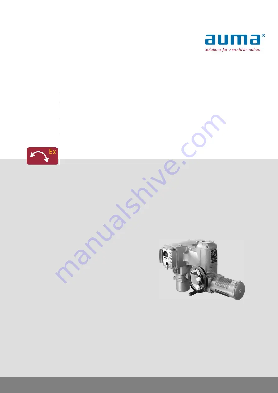
AUMA SGExC 05.1 Скачать руководство пользователя страница 1

Control

→ 

Parallel

Profibus DP

Modbus

DeviceNet

Foundation Fieldbus

Part-turn actuators

SGExC 05.1 – SGExC 12.1

Control unit: electronic (MWG)

with actuator controls

AUMATIC ACExC 01.1 Non-Intrusive

Assembly, operation, commissioning

Operation instructions

Содержание SGExC 05.1

Страница 1: ...s DP Modbus DeviceNet Foundation Fieldbus Part turn actuators SGExC 05 1 SGExC 12 1 Control unit electronic MWG with actuator controls AUMATIC ACExC 01 1 Non Intrusive Assembly operation commissioning...

Страница 2: ...es and symbols 8 2 Identification 8 2 1 Name plate 9 2 2 Short description 11 3 Transport storage and packaging 11 3 1 Transport 11 3 2 Storage 11 3 3 Packaging 12 4 Assembly 12 4 1 Mounting position...

Страница 3: ...ignals analogue 34 9 Commissioning basic settings 34 9 1 Heat up time for low temperature version 34 9 2 End stops in part turn actuator 35 9 2 1 End stop CLOSED set 36 9 2 2 End stop OPEN set 36 9 3...

Страница 4: ...ns 64 12 4 Accessories 64 12 5 Further information 65 13 Spare parts 65 13 1 Part turn actuators SGExC 05 1 SGExC 12 1 via plug socket connector with screw type terminals KP KPH 67 13 2 Actuator contr...

Страница 5: ...o special regulations which have to be observed The end user or contractor of the plant are responsible for respect and control of these regulations standards and laws Commissioning Prior to commissio...

Страница 6: ...s are only valid for the clockwise closing standard version i e driven shaft turns clockwise to close the valve 1 3 Warnings and notes The following warnings draw special attention to safety relevant...

Страница 7: ...within the menu to the parameter By using the push buttons of the local controls you may quickly find the desired parameter in the display Step by step Provides a detailed description of each step for...

Страница 8: ...4 Additional plate e g KKS plate Power Plant Classification System 5 Explosion protection approval plate Data for identification Figure 2 Actuator name plate 1 Type and size of actuator 2 Commission...

Страница 9: ...EN ISO 5211 A part turn actuator is an actuator which transmits a torque to the valve for less than one full revolution It need not be capable of withstanding thrust AUMA part turn actuators are driv...

Страница 10: ...etting is performed via the controls actuator and controls housings do not have to be opened For this purpose the actuator is equipped with an MWG magnetic limit and torque transmitter also supplying...

Страница 11: ...st and dirt Apply suitable corrosion protection agent to uncoated surfaces Damage on display caused by temperatures below permissible level The AUMATIC actuator controls must NOT be stored below 30 C...

Страница 12: ...ove cap nut 1 and pull out ball handle 2 2 Insert ball handle 2 in correct position and fasten with cap nut 1 3 After ball handle fitting remove label from handwheel 4 3 Part turn actuator to valve mo...

Страница 13: ...ounting position is end position OPEN 2 Thoroughly degrease mounting faces of the mounting flange 3 Apply a small quantity of grease to the valve shaft 2 4 Place coupling 1 onto valve shaft 2 and secu...

Страница 14: ...7 M12 4 4 Mounting positions of local controls The mounting position of the local controls is selected according to the order If after mounting the actuator to the valve or the gearbox on site the loc...

Страница 15: ...cover during fitting 1 Loosen screws and remove the local controls 2 Check whether O ring is in good condition correctly insert O ring 3 Turn local controls into new position and re place Cable damag...

Страница 16: ...aximum permissible protection max protection Rated power Switchgear 16 A gL gG up to 1 5 kW Reversing contactor A1 If controls are mounted separately from actuator controls on wall bracket Consider le...

Страница 17: ...tor name plate Figure 10 Motor name plate example 1 Type of current 2 Mains voltage 3 Mains frequency for 3 ph and 1 ph AC motors Connecting cables For device insulation appropriate voltage proof cabl...

Страница 18: ...glands 5 2 2 Cable connection Table 5 Terminal cross sections and tightening torques Tightening torques Terminal cross sections Type 2 Nm 1 5 1 2 5 6 mm flexible or solid Power terminals U1 V1 W1 PE c...

Страница 19: ...ble 2 PE connection motor cable Danger of corrosion Damage due to condensation After mounting commission the device immediately to ensure that heater mini mises condensation Information Some actuators...

Страница 20: ...nt Type of protection Ex e 5 Terminal compartment Type of protection Ex d 6 Frame Hazardous voltage Risk of electric shock Disconnect device from the mains before opening 1 Loosen screws 2 and remove...

Страница 21: ...agram In case of a fault Hazardous voltage while protective earth conductor is NOT connected Risk of electric shock Connect all protective earth conductors Connect PE connection to external protective...

Страница 22: ...r serious injury Handle cover and housing parts with care Joint surfaces must not be damaged or soiled in any way Do not jam cover during fitting 5 Fit cover 1 and fasten screws 2 evenly crosswise 5 4...

Страница 23: ...K customer plug XA XM XK refer to wiring diagram these connecting cables must be subject to an insulation test in compliance with EN 50178 Connecting cables for MWG do not belong to this group They ma...

Страница 24: ...el during motor operation extends or reduces the operating time depending on the direction of rotation 6 1 2 Manual operation disengage Release handwheel A spring pulls back the handwheel into the ini...

Страница 25: ...tton STOP 2 Run actuator in direction CLOSE Press push button CLOSE 3 Information The OPEN CLOSE operation commands can be given either in push to run opera tion mode or in self retaining mode In self...

Страница 26: ...0 OFF Now settings and indications can be performed via the push buttons 1 4 6 3 1 Short overview Functions of the push buttons Functions Push but tons Scrolling within a group The triangles in the di...

Страница 27: ...the display indicate which direction of scrolling within one group is possible 6 4 Password entry In the menu group M the settings are password protected To change the parameters a password must be e...

Страница 28: ...Step by step 1 Set selector switch to position 0 OFF 2 Press C and hold it down for approx 3 seconds Display indicates MAIN MENU M0 LANGUAGE CONTRAST SETTINGS OPERATIONAL DATA 3 Press Display indicate...

Страница 29: ...e EDIT M010 LANGUAGE ENGLISH EDIT C ESC 8 Press again to enter the edit mode Display indicates EDIT M010 LANGUAGE ENGLISH EDIT OK C ESC 9 Set new value Press 10 Accept value or cancel Accept value Pre...

Страница 30: ...d set point display Line 2 indicates currently incoming operation commands OPEN STOP CLOSE or the setpoints E1 or E7 for actuators equipped with positioner process controller in of the total travel LO...

Страница 31: ...information please refer to the Manual Operation and setting 7 1 3 Torque indication edit The torque value can be displayed in percent Newtonmeter Nm or in Lbs ft Via the menu to parameter MAIN MENU...

Страница 32: ...rection OPEN blinking Bluetooth connection available illuminated LED 6 BT option Information The behaviour blinking illuminated can be changed via the BLINKER M1311 parameter 7 3 Mechanical position i...

Страница 33: ...default value FAULT GROUP 3 fault signal includes torque fault thermal fault phase failure and internal faults Default values OUTPUT CONTACT 1 to OUTPUT CONTACT 5 OUTPUT CONTACT 1 CLOSED POSITION OUTP...

Страница 34: ...uator and the controls are not live and have cooled down to ambient temperature Under these conditions and after connection to the voltage supply the following heat up times must be complied with prio...

Страница 35: ...screws 1 with approx 3 turns 2 Move valve to end position CLOSED with handwheel Check whether end stop nut 2 rotates simultaneously Otherwise Turn end stop nut 2 clockwise until end stop is reached 3...

Страница 36: ...than the valve end position 5 Fasten screws 1 crosswise at 25 Nm Subsequent to this setting the limit switching for end position OPEN can be set refer to Limit switching set chapter For this the switc...

Страница 37: ...EN 3 3 Turn end stop nut 2 clockwise until it is tight up to the travelling nut 4 4 Swing angle reduction 4 1 Move valve manually to the desired end position OPEN 4 2 Turn end stop nut 2 clockwise unt...

Страница 38: ...ng will trip shortly before reaching the set tripping torque If this is not the case one of the following fault signals is displayed TSO FAULTS or TSC FAULTS menu S1 Via the menu to parameter MAIN MEN...

Страница 39: ...g 8 Press Display indicates VIEW M1100 OPEN POSITION CLOSED POSITION VIEW M1101 OPEN POSITION CLOSED POSITION Use and to select between OPEN POSITION and CLOSED POSITION 9 Press Display indicates VIEW...

Страница 40: ...TION CLOSED POSITION EDIT M1111 OPEN POSITION CLOSED POSITION Use and to select between OPEN POSITION and CLOSED POSITION 14 Press Display shows the set value EDIT M1110 OPEN POSITION LIMIT EDIT C ESC...

Страница 41: ...o status display Press C several times until S0 is displayed 9 5 Torque switching check set Once the set torque is reached the torque switches will be tripped overload protection of the valve Informat...

Страница 42: ...SETTINGS OPERATIONAL DATA 3 Press Display indicates MAIN MENU M1 LANGUAGE CONTRAST SETTINGS OPERATIONAL DATA 4 Press Display indicates SETTINGS M10 SET LIMIT SWITCHES SEATING MODE TORQUE 5 Press twice...

Страница 43: ...elect between OPENING and CLOSING 9 Press Display indicates VIEW OPENING 65 C ESC VIEW CLOSING 65 C ESC Use and to also select here between OPENING and CLOSING 10 Return to the VIEW EDIT menu Press C...

Страница 44: ...ect between OPENING and CLOSING Information The value can be displayed in percent Newtonmeter Nm or in Lbs ft To display in percent 100 equals the max torque indicated on the name plate of the actuato...

Страница 45: ...UE FAULT OPEN or TORQUE FAULT CLOSE torque fault The fault has to be acknowledged before the operation can be resumed The acknowledgement is made either by an operation command in the opposite directi...

Страница 46: ...SWORD 0 EDIT OK C ESC 6 Enter password Press 4 x 0000 default factory password The current actuator position is displayed SET LIMIT SWITC M100 CLOSED POSITION 63 3 EDIT C ESC SET LIMIT SWITC M101 OPEN...

Страница 47: ...N 0 0 EDIT C ESC Use to select OPEN POSITION Setting end position OPEN 13 Press to enter the edit mode Display indicates SET LIMIT SWITC M101 OPEN POSITION ACCEPT C ESC 14 Engage manual operation 15 T...

Страница 48: ...sly described have been performed 9 7 1 Direction of rotation check Valve damage due to incorrect direction of rotation If the direction of rotation is wrong switch off immediately press STOP Eliminat...

Страница 49: ...EN or TORQUE FAULT CLOSE 3 If the end position setting is incorrect Reset limit switching 9 8 Switch compartment open The switch compartment must be opened to perform the following settings options Fl...

Страница 50: ...joint surfaces with an acid free corrosion protection agent 3 Check whether O ring 3 is in good condition replace if damaged 4 Apply a thin film of non acidic grease e g petroleum jelly to the O ring...

Страница 51: ...in any way Do not jam cover during fitting Danger of corrosion due to damage to paint finish Touch up damage to paint finish after work on the device 1 Unfasten motor cover 1 2 Set required operating...

Страница 52: ...tuator operation They only serve for information purposes Fault and warning indications are shown in the display 10 2 1 Status indication S0 faults and warnings Line 4 of status indication S0 displays...

Страница 53: ...L FAULT If the fault indication display persists after cooling down Set selector switch to position Local control LOCAL or reset fault indication via push button Reset Check fuse F4 For further inform...

Страница 54: ...nal loss of setpoint SETPOINT E1 LOSS Check wiring Signal loss of torque source TORQUE E6 LOSS 10 2 4 Status indication S3 causes for not ready remote The causes for the NOT READY IND fault signals fr...

Страница 55: ...ge output power supply unit 115 V F5 Automatic reset fuse as short circuit protection for external 24 V DC supply for customer see wiring diagram Information After fuse replacement replace and fasten...

Страница 56: ...For further information to this topic please refer to the Manual Operation and setting 56 SGExC 05 1 SGExC 12 1 Control unit electronic MWG Corrective action ACExC 01 1 Non Intrusive...

Страница 57: ...etc have to be checked for correct tightness and sealing Respect torques according to manufacturer s details Check fastening screws between actuator and gearbox valve for tightness If required fasten...

Страница 58: ...ance intervals After 3 years at the latest for Ex certified products Lubrication In the factory the gear housing is filled with grease Change of grease or re lubrication will be required in case of lu...

Страница 59: ...e checked All cable and motor protection components have to be checked If defects impairing the safety are detected during maintenance repair measures have to be initiated without delay Any kind of su...

Страница 60: ...dard PTC thermistors according to DIN 44082 Option Thermoswitches NC Motor protection Magnetic limit and torque transmitter MWG Limit switching Via MWG like limit switching Torque switching Via MWG Po...

Страница 61: ...EN end position CLOSED selector switch in REMOTE torque fault CLOSE torque fault OPEN 1 potential free change over contact max 250 V AC 5 A resistive load for collective fault signal Default configura...

Страница 62: ...the control range Change over between open close duty and modulating duty via digital MODE input Functions Programmable monitoring of the max number of starts generates warning signal Reaction monitor...

Страница 63: ...as well as ON and OFF time 1 up to 300 seconds can be programmed individually for the directions OPEN and CLOSE Timer Any 8 intermediate positions between 0 and 100 reaction and signal behaviour progr...

Страница 64: ...4 Accessories AUMATIC mounted separately from the actuator including plug socket connector Connecting cables on request Recommended for high ambient temperatures difficult access or in case of heavy v...

Страница 65: ...are parts 13 1 Part turn actuators SGExC 05 1 SGExC 12 1 via plug socket connector with screw type terminals KP KPH 65 SGExC 05 1 SGExC 12 1 Control unit electronic MWG ACExC 01 1 Non Intrusive Spare...

Страница 66: ...al 501 3 Washer for power terminal 501 4 Sub assembly Pin carrier without pins 502 0 Sub assembly Pin for controls 505 0 Sub assembly Pin for motor 506 0 Sub assembly Plug cover 507 0 Coupling 525 0 S...

Страница 67: ...13 2 Actuator controls AUMATIC ACExC 01 1 via plug socket connector with screw type terminals KP KPH 67 SGExC 05 1 SGExC 12 1 Control unit electronic MWG ACExC 01 1 Non Intrusive Spare parts...

Страница 68: ...6 0 Interface board 008 1 Sub assembly Logic board 009 0 Relay board 011 1 Sub assembly Cover 500 0 Sub assembly Terminal board 501 0 Screw for control terminal 501 1 Washer for control terminal 501 2...

Страница 69: ...13 3 Actuator controls AUMATIC ACExC 01 1 with plug socket connector and terminal blocks KES 69 SGExC 05 1 SGExC 12 1 Control unit electronic MWG ACExC 01 1 Non Intrusive Spare parts...

Страница 70: ...embly Power supply 006 0 Interface board 008 1 Sub assembly Logic board 009 0 Relay board 011 1 Sub assembly Cover 500 0 Sub assembly Pin carrier without pins 502 0 Sub assembly Pin for controls 505 0...

Страница 71: ...14 Certificates 14 1 Declaration of Incorporation and EC Declaration of Conformity 71 SGExC 05 1 SGExC 12 1 Control unit electronic MWG ACExC 01 1 Non Intrusive Certificates...

Страница 72: ...14 2 ATEX certificate 72 SGExC 05 1 SGExC 12 1 Control unit electronic MWG Certificates ACExC 01 1 Non Intrusive...

Страница 73: ...73 SGExC 05 1 SGExC 12 1 Control unit electronic MWG ACExC 01 1 Non Intrusive Certificates...

Страница 74: ...74 SGExC 05 1 SGExC 12 1 Control unit electronic MWG Certificates ACExC 01 1 Non Intrusive...

Страница 75: ...on 8 Indication lights 31 Indications 30 Indicator disc 32 49 Inspection record 9 Intrusive 10 L LEDs 31 Language in the display 28 Limit switching 45 48 Local control 24 Local controls 24 Low tempera...

Страница 76: ...play 30 Storage 11 Support 57 Swing angle 36 T Technical data 60 Terminal cross sections 17 20 Terminal plan 16 Test run 48 Tightening torques 17 20 Torque indication 31 31 Torque switching 41 Transpo...

Страница 77: ...marussia auma ru www auma ru ERICHS ARMATUR AB SE 20039 Malm Tel 46 40 311550 Fax 46 40 945515 info erichsarmatur se www erichsarmatur se GR NBECH S NNER A S DK 2450 K benhavn SV Tel 45 33 26 63 00 Fa...

Страница 78: ...AUMA JAPAN Co Ltd JP 211 0016 Nakaharaku Kawasaki shi Kanagawa Tel 81 44 863 8371 Fax 81 44 863 8372 mailbox auma co jp www auma co jp AUMA ACTUATORS Singapore Pte Ltd SG 569551 Singapore Tel 65 6 481...

Страница 79: ...79 AUMA worldwide...

Страница 80: ...r GmbH Co KG P O Box 1362 D 79373 Muellheim Tel 49 7631 809 0 Fax 49 7631 809 1250 riester auma com www auma com Y003 148 003 en 4 12 For detailed information on AUMA products refer to the Internet ww...

Отзывы: