-
installer
GIALIX 24 MA C -BC
manual
-
8
3 - INSTALLATION
3.1 - Hydraulic schematic diagrams
3.2 - Installation recommendations
The
Gialix
electric boiler is designed to operate directly on
a radiator circuit (100
o
C safety aquastat and maximum boiler
temperature - TCMA at parameter n°
02
to 80°C).
For adaptation to a low temperature underfloor heating network:
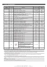
see § «Settings for a low temperature application» and § «Setting
the regulator»).
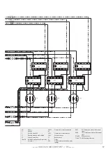
3.1.1 - DIrect heating circuit
3.1.2 - Direct heating circuit
(without mixing valves)
+ 1 DHW circuit
Without mixing valves.
or
Radiator circuit
Electric boiler
Underfloor
heating
circuit
OR
1
: 3-speed circulator
2
: 8 L expansion vessel
3
: Safety valve set at 3 bars
4
: Stop valves
5
: Automatic air purgers
6
: Water pressure sensor
7
: Backflow prevention device
8
: DHW loop circulator pump
D
: Heating outlet 1’’ female
R
: Heating inlet 1’’ female
Rm
: Manual valve (piece with ambient temperature thermostat TA)
Rt
: Thermostatic mixing valve
TA
: Ambient temperature thermostat with or without timer or ambient
temperature sensor SA
SExt : Exterior sensor
EFS
: Domestic cold water
AqECS : Domestic hot water aquastat
or
SECS : Domestic hot water sensor
V3V : 3-way valve with counter spring
ECS : Domestic hot water
LTP
: Underfloor heating 65°C temperature limiter with manual reset
(mandatory)
or
or
Radiator circuit
Underfloor
heating
circuit
Electric boiler
Domestic hot water
production tank
OR
•
Backflow prevention device
French law requires that a backflow prevention device be
fitted onto the installation. Please check the current laws and
regulations in effect in the country of installation to ensure that
the installation is in compliance.
The backflow prevention devices must be installed at various
non-regulated pressure zones. It serves to prevent incoming
heating water from entering the drinking water circuit.
The backflow prevention device must be connected to the mains
drainage network.
• Cross-sections, markings, and purging of the heating
networks
A sufficient flow rate must be ensured so that the difference
in temperature between the outlet and inlet points does not
exceed 20°C. In the case of an installation with thermostatic
mixing valves, this inspection must be carried out with all valves
open.
The power actually needed will determine the heating water
flow rate, and thus, the distribution network calculation.
Adjust the pump speed to the characteristics of the hydraulic
circuit using the provided flow rate curves/pressure.
Содержание 132616
Страница 3: ... installer GIALIX 24 MA COMFORT BCmanual 3 ...
Страница 31: ... installer GIALIX 24 MA COMFORT BCmanual 31 ...


