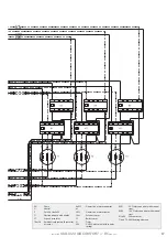
-
installer
GIALIX 24 MA C -BC
manual
-
-
installer
GIALIX 24 MA C -BC
manual
-
13
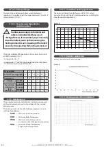
Under no circumstances can the manufacturer be held liable for
consequences arising from the incorrect choice of cable widths
for the power supply cables, or the installation method and
specifications used.
Example of determination based on standard C15-100:
- Ambient temperature: 20°C
- Type of cable: U1000 R02V
- Length < 15 m
- Installation without gaskets and with a well ventilated
cable channel
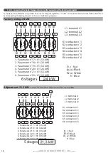
Gialix
Maximum power
P1
Fuse sizes for
mains switch
24 kW -400V three-
phase-
24 kW
50 A
Gialix
Maximum
power
P1
MINIMUM width per phase in mm²
and number of conductors for this
example
24 kW
-400V three-
phase-
24 kW
L1 = Phase = 10²
L2 = Phase = 10²
L3 = Phase = 10²
N = Phase = 10²
4 x 10² + T *
* The width of the ground cable must be equal to the width of the largest
supply cable.
Gialix
Maximum
power
P1
MAXIMUM width per phase in
mm²
and number of conductors for
this example
24 kW
-400V three-
phase-
24 kW
4 x 16² + T *
* The width of the ground cable must be equal to the width of the largest
supply cable.
3.6.1.3 - Fuse size
3.6.2 - Electrical connection terminals
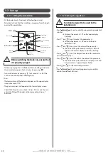
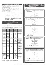
The terminal strips are spring loaded «CAGE CLAMPs»
For handling:
- For 2.5mm² control terminals use a 3.5 x 0.5 mm flathead
screwdriver
- For 10mm² or 16mm² mains power terminals, use a 5.5 x 0.8
mm flathead screwdriver
- For 4mm² intermediary power terminals, use a 3.5 x 0.5 mm
flathead screwdriver.
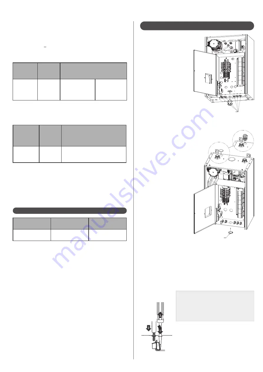
Placement of the cable clamp
(provided with the boiler) for
input of the power supply
cable on the lower part of the
installation.
5 cable clamp imputs for control cables
(ambient temperature sensor, exterior or domestic sensors
and load shedding)
OR
Placement of the cable clamp
(provided with the boiler) for
input of the power supply
cable at the higher part of the
installation.
Remove the plastic cap and
place it on the lower part of
the installation.
Plastic cap to
reposition
Note:
The wires must be stripped to the
following lengths:
- between 10 and 12 mm for the 2.5² control
terminals.
- between 17 and 20 mm for the mains
power terminals.
1
: Insert the screwdriver in to the flap just above or
below the identification number.
2
: Insert the wire into the «Cage Clamp» once it is
open.
3
: Remove the screwdriver.
Содержание 132616
Страница 3: ... installer GIALIX 24 MA COMFORT BCmanual 3 ...
Страница 31: ... installer GIALIX 24 MA COMFORT BCmanual 31 ...


