


2-2
FLEXNET – FNER Expandable (Modular) Routing Switches – Installation & Operation Manual
CHAPTER 2: CONNECTIONS & PROTOCOLS
3
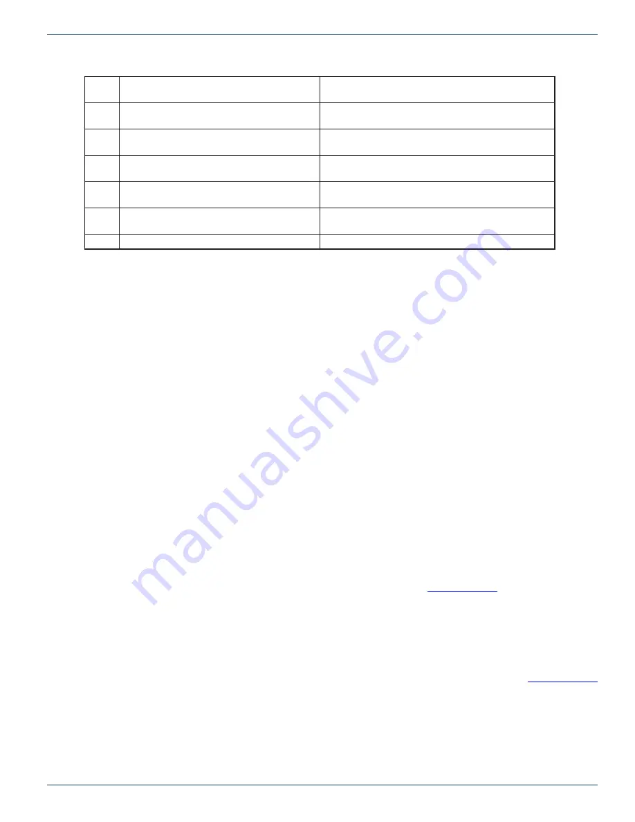
RXD
(receive data)
Non-inverting Transmit
4
DTR
(data terminal ready)
Non-inverting Receive
5
GND
(signal gound)
GND
6
DSR
(data set ready)
Inverting Transmit
7
CTS
(clear to send)
Not used
8
RTS
(request to send)
Not used
9
Not used
Inverting Receive
Table 1: 8x1 Control Module Control In Port Pin Definitions
2.4 MPC 128 Control In Port Connection
If you are using a computer to control the FNER, you can use a direct serial connection to the Control In port. For serial control,
connect a serial cable (RS-232 or RS-422/485) from the computer to the 9-pin SERIAL port on the rear panel of the MPC 128.
The connector is shared for both RS-232 and RS-422/485. Do NOT use a NULL MODEM adapter or crossover cable. Use a
straight through 1 to 1 cable.
2.4.1 MPC 128 Control In Serial Communication Settings
The serial port parameters are the same whether you are using RS-232, RS-422 or RS-485. The parameters are fixed at 9600
baud, 8 data bits, no parity, and 1 stop bit (8N1). The command protocol for controlling the switch is provided in the appendix.
2.4.2 MPC 128 Control In RS-232 Description
RS-232 was designed for communication of local devices, and supports one transmitter and one receiver. This standard
uses single ended signals over unbalanced, unterminated wires. Single ended means the signal is sent over one wire with
respect to a single ground source. Unterminated means the signal lines do not have impedance matching at the line ends. This
interface is useful for point-to-point communication at slow speeds and over short lengths of cable. Most PCs come equipped
with one or more RS-232 serial ports.
2.4.3 RS-232 Advantages/Disadvantages
RS-232 is easy to implement and has been standardized and accepted for years. Due to the nature of RS-232, the signals are
susceptible to noise and grounding problems. These problems set a limit to cable lengths. Quintech recommends if using RS-
232 that the cable length be limited to 20 meters or approximately 60 feet. RS-232 is also only point-to-point communications
so only two devices will typically communicate with each other over the RS-232 standard.
2.4.4 MPC 128 Control In RS-422 Description
In RS-422 communications, a pair of twisted wires is used to carry a signal. The data is encoded and decoded as a differential
voltage between the two lines. As a differential voltage, in principle the interface is unaffected by differences in ground voltage
between sender and receiver. For more details on differential signaling, refer to the
of this document.
2.4.5 RS-422 Advantages/Disadvantages
RS-422 differential signals over twisted pair wires are less affected by noise. They therefore can communicate at faster rates
and over longer distances. RS-422 is better than RS-232 but it still is limited to one master and up to ten receivers on the bus.
Recommended maximum length is 4000 feet. The FLEXNET RS-422 standard is limited to 10 receivers.
2.4.6 MPC 128 Control In RS-485 Description
The MPC 128 can be configured to communicate in RS-485 standard. For all RS-485 information, refer to the
of this document.
2.4.7 All Control Port Connections except MPC Control In
Before powering up the units, make sure all of the control cables are properly installed. All FNER modules should be daisy-
chained together, with the MPC 128 unit occupying the first position in the chain. Connect the CONTROL OUT port of the
MPC 128 to the CONTROL IN port of the first 16x1 module in the chain. The CONTROL OUT port of that module connects to
the CONTROL IN port of the next 16x1 module, etc. The last module in the chain will have an unused 9-pin connector labeled
CONTROL OUT.


