25
ATmega103(L)
0945G–09/01
$0028
jmp
UART_TXC
; UART TX Complete Handler
$002A
jmp
ADC
; ADC Conversion Complete Handler
$002C
jmp
EE_RDY
; EEPROM Ready Handler
$002E
jmp
ANA_COMP
; Analog Comparator Handler
;
$0030
MAIN:
ldi
r16, high(RAMEND); Main program start
$0031
out
SPH,r16
$0032
ldi
r16, low(RAMEND)
$0033
out
SPL,r16
$0034
<instr>
xxx
...
...
...
...
Reset Sources
The ATmega103(L) has three sources of reset:
•
Power-on Reset. The MCU is reset when the supply voltage is below the Power-on
Reset threshold (V
POT
).
•
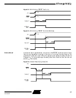
External Reset. The MCU is reset when a low level is present on the RESET pin for
more than 50 ns.
•
Watchdog Reset. The MCU is reset when the Watchdog timer period expires and
the Watchdog is enabled.
During reset, all I/O registers except the MCU Status Register are then set to their initial
values and the program starts execution from address $0000. The instruction placed in
address $0000 must be a JMP (absolute jump) instruction to the reset handling routine.
If the program never enables an interrupt source, the interrupt vectors are not used and
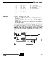
regular program code can be placed at these locations. The circuit diagram in Figure 23
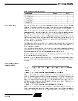
shows the reset logic. Table 5 defines the timing and electrical parameters of the reset
circuitry.
Figure 23.
Reset Logic
Power-on Reset
Circuit
Reset Circuit
Watchdog
Timer
On-chip
RC Oscillator
Delay Unit
Q
Q
S
R
INTERNAL
RESET
POR
VCC
XTAL1
RESET
PEN
D
Q
E
100-500K
10-50K
COUNTER RESET
SUT0
SUT1
Q8
Q11 Q13
14-stage Ripple Counter


