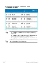
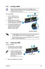
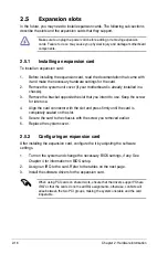
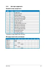


2-28
Chapter 2: Hardware information
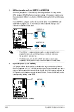
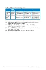
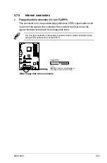
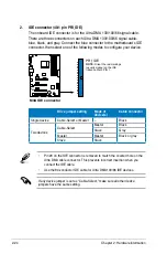
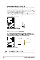
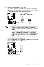
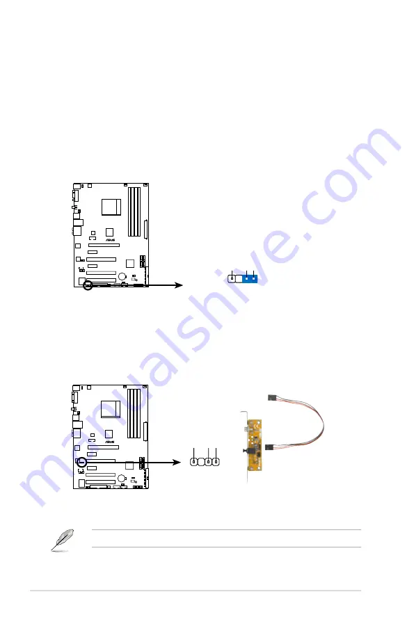
6. Chassis intrusion connector (4-1 pin CHASSIS)
This connector is for a chassis-mounted intrusion detection sensor or switch.
Connect one end of the chassis intrusion sensor or switch cable to this
connector. The chassis intrusion sensor or switch sends a high-level signal to
this connector when a chassis component is removed or replaced. The signal
is then generated as a chassis intrusion event.
By default , the pin labeled “Chassis Signal” and “Ground” are shorted with
a jumper cap. Remove the jumper caps only when you intend to use the
chassis intrusion detection feature.
M3A
®
M3A Chassis intrusion connector
CHASSIS
+5VSB_MB
Chassis Signal GN
D
(Default)
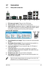
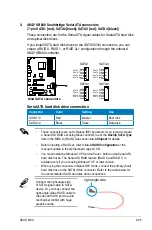
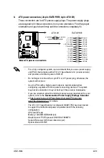
7. Digital audio connector (4-1 pin SPDIF_OUT)
This connector is for an additional Sony/Philips Digital Interface (S/PDIF)
port(s). Connect the S/PDIF Out module cable to this connector, then install
the module to a slot opening at the back of the system chassis.
The S/PDIF module is purchased separately.
M3A
®
M3A Digital audio connector
+5V
SPDIFOUT GND
SPDIF_OUT
Содержание M3A - Motherboard - ATX
Страница 1: ...Motherboard M3A ...
Страница 13: ...1 Product introduction This chapter describes the motherboard features and the new technologies it supports ...
Страница 14: ...ASUS M3A Chapter summary 1 1 1 Welcome 1 1 1 2 Package contents 1 1 1 3 Special features 1 2 ...
Страница 56: ...ASUS M3A Chapter summary 3 3 1 Starting up for the first time 3 1 3 2 Turning off the computer 3 2 ...
Страница 98: ...4 38 Chapter 4 BIOS setup ...
Страница 134: ...5 34 Chapter 5 Software support ...


