


2-24
Chapter 2: Hardware information
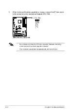
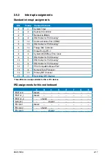
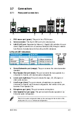
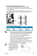
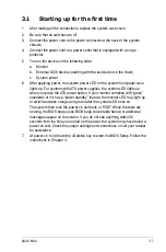
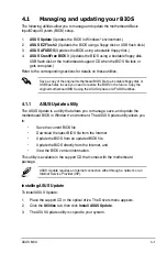
2. IDE connector (40-1 pin PRI_IDE)
The onboard IDE connector is for the Ultra DMA 133/100/66 signal cable.
There are three connectors on each Ultra DMA 133/100/66 signal cable:
blue, black, and gray. Connect the blue connector to the motherboard’s IDE
connector, then select one of the following modes to configure your device.
• Pin 20 on the IDE connector is removed to match the covered hole on the
Ultra DMA cable connector. This prevents incorrect insertion when you
connect the IDE cable.
• Use the 80-conductor IDE cable for Ultra DMA 100/66 IDE devices.
If any device jumper is set as “Cable-Select,” make sure all other device
jumpers have the same setting.
Drive jumper setting
Mode of
device(s)
Cable connector
Single device
Cable-Select or Master
–
Black
Two devices
Cable-Select
Master
Black
Slave
Gray
Master
Master
Black or gray
Slave
Slave
M3A
®
M3A IDE connector
NOTE:
Orient the red markings
(usually zigzag) on the IDE
ribbon cable to PIN 1.
PRI_IDE
Содержание M3A - Motherboard - ATX
Страница 1: ...Motherboard M3A ...
Страница 13: ...1 Product introduction This chapter describes the motherboard features and the new technologies it supports ...
Страница 14: ...ASUS M3A Chapter summary 1 1 1 Welcome 1 1 1 2 Package contents 1 1 1 3 Special features 1 2 ...
Страница 56: ...ASUS M3A Chapter summary 3 3 1 Starting up for the first time 3 1 3 2 Turning off the computer 3 2 ...
Страница 98: ...4 38 Chapter 4 BIOS setup ...
Страница 134: ...5 34 Chapter 5 Software support ...


