


5.0
Operation
5.1
Shutdown
The unit may be shut down by turning the AC input and DC output breakers “off” in any sequence.
5.2
Start-up
Confirm the operating voltage before proceeding. On units equipped with selectable input voltages,
please confirm the jumper selection on both terminal blocks with the AC operating voltage.
To start the unit after a repair or for the first time, the procedure as outlined in the initial start-up
section of this manual should be followed. Routine start-up is accomplished by first turning the AC
input breaker “on” and then turning the DC output breaker “on”. This sequence is not critical but it
allows a more controlled charging of the DC output filter capacitors.
5.3
Normal Mode
Normal operation of the rectifier will be in the “Float” mode. The “Power on” and “Float” indicator will
be illuminated. The display panel meter will be indicating the output current and when the display
mode select control is depressed the display will indicate the output voltage level. Depending on the
current limit setting or load, the current limit indicator may be “on”.
5.4
Float/Equalize/Test
When the AC power is applied the unit may be operated in the “Float” ,"Equalize" or “Test” modes.
Mode status is indicated by the corresponding indicator on the panel. “Float” is the default mode
from start up. “Test” Mode must be manually selected whereas equalize may be selected remotely.
The receipt of a remote “Equalize” signal will put the unit in the “Equalize” mode. Upon removal of
the signal, the unit will return to the “Float” mode.
5.5
Fuse Replacement
WARNING: AC power to the unit must be removed before blown fuses
can be replaced.
WARNING: DC power may be stored up to five minutes at some points
inside the unit.
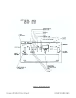
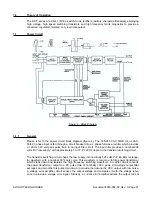
The fuses located on the front underside of the main power board are a extra safety precaution to
protect the auxiliary power supply. As covered in the power circuit theory of operation, the auxiliary
supply provides line power to the pulse width modulator circuit and the front panel control board.
Under normal circumstances the fuses will not be stressed. Only under a severe situation, such as
a short in the auxiliary supply will the fuses blow.
ARGUS TECHNOLOGIES
Document #010-002-C0 Rev. H Page 15
Содержание RST 48/30
Страница 1: ...RST 48 30 Switched Mode Rectifier Eliminator 010 006 B0 ...
Страница 24: ...Document 010 002 C0 Rev H Page 14 ARGUS TECHNOLOGIES Figure 3 Front Panel Layout ...
Страница 52: ......
Страница 53: ......
Страница 63: ......
Страница 75: ......


