


3.3.02
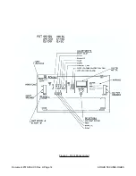
Indicators
The indicators provide visual indication of operational status and alarms. The indicators and associ-
ated colors are:
Power On . . . . . . . . . . . . . Green
Float Mode . . . . . . . . . . . . Green
Equalize Mode . . . . . . . . . Yellow
Test Mode . . . . . . . . . . . . Red
Rectifier Fail . . . . . . . . . . . Red
Under Voltage Alarm . . . . . Red
Current Limit . . . . . . . . . . Yellow
OVP Trip . . . . . . . . . . . . . Red
3.3.03
Power On Indicator
When AC power is present and the AC input circuit breaker placed in the “on” position the indicator
will light. The indicator will not illuminate if the AC input is removed.
3.3.04
Float Mode
Normal operation of the rectifier is in the “Float” mode which the rectifier will default to when AC
power is supplied to the unit. When in the “Float” mode the output voltage of the rectifier is deter-
mined by the “Float” mode adjustment control setting. The “Float” mode control button manually re-
turns the unit to the “Float” mode from a locally initiated “Equalize” or “Test” mode and is indicated
by illumination of the “Float” indicator.
3.3.05
Equalize Mode
When the unit is required to equalize a battery string, the “Equalize” mode is generally used and is
indicated by illumination of the “Equalize” indicator. This mode can be entered manually via the
front panel control or by an external signal supplied via the external “Equalize” input. When in the
“Equalize” mode the output voltage is set by the “Equalize” voltage control adjustment.
3.3.06
Test Mode
Selection of the “Test” mode is via the mode switch on the front panel and is indicated by illumina-
tion of the “Test” indicator. The output breaker must be in the open position before this mode can
be selected. Once in the “Test” mode the output circuit breaker can be closed and the unit operated
under control of the “Test” adjustment potentiometer. When in the “Test” mode the unit’s alarm lev-
els can be set with the output breaker open without disturbing a system which is powered by a bat-
tery or other rectifiers operating in parallel. The output voltage of the unit is set by the “Test” adjust-
ment potentiometer. This feature is useful for operating the unit while it is isolated from other units
in a multi-rectifier system or from the battery.
3.3.07
Alarms
The unit’s three alarms, Rectifier Fail, Low Voltage, and Current Limit are extended via “form C”
contacts for remote monitoring. Visual indication of the alarms is active during all modes of opera-
tion. Rectifier fail alarm discrimination circuitry is factory set. However, the Under voltage alarm is
user adjustable. All alarms are “real time” and therefore do not latch. The Rectifier Fail and Low
Voltage alarm contacts are “fail safe” and therefore will signal an alarm without DC present (i.e. a
battery), however, the indicators will not remain illuminated unless there is DC power available (i.e.
a battery or a second operational unit in parallel).
ARGUS TECHNOLOGIES
Document #010-002-C0 Rev. H Page 3
Содержание RST 48/30
Страница 1: ...RST 48 30 Switched Mode Rectifier Eliminator 010 006 B0 ...
Страница 24: ...Document 010 002 C0 Rev H Page 14 ARGUS TECHNOLOGIES Figure 3 Front Panel Layout ...
Страница 52: ......
Страница 53: ......
Страница 63: ......
Страница 75: ......


