


Remove the jumpers from the main input voltage selector ternimnal block (located beside the input
circuit breaker) and the auxiliary power block (TB2, located on front edge of the power printed cir-
cuit board). Reinstall the jumpers for the new voltage as follows:
Voltage
Main Block
Auxiliary Block
120V
1-2
1-2
3-4
3-4
5-6
240V
2-3
2-3
4-5
If jumpers have to be fabricated, use #10 AWG for the main terminal block and #20 AWG for the
auxiliary block. The unit voltage configuration change is now complete.
4.5
Output Connections
WARNING: Ensure output breaker is “off” before attempting work on
the output cable assembly. When the unit is connected to batteries,
another operating rectifier or a grounded load, the output leads must
be suitably taped to prevent contact with the unit or each other. Dis-
connect the battery externally if possible.
4.5.1
Users of this equipment should be aware of the short circuit current capacity of the connected bat-
tery system in relation to the interrupting capacity of the output breaker. In applications where the
battery system short circuit current may exceed the breaker’s interrupting capacity, the battery ca-
bles should be protected by a high interrupting capacity fuse or breaker. The current limiting capac-
ity of the battery system can be aided by selecting the minimal wire size without compromising the
maximum loop voltage drop.
DC output wire must be UL approved File # B64801, XHHW or RHH/RHW (Canadian users; RW90
Type). See specifications for recommended wire gauge. Control and sense wires must be UL ap-
proved Style 1015 (Canadian users; TEW type). Select either rear or front entry of the cables and
swap the blank plate with the holed plate if necessary. For ease of cable manipulation, the cable
clamp plate should not be mounted until the end of this sequence. Feed the cable assembly
through the hole in the plate. The output cables, sense, control and alarm wires should be bundled
together. If the remote sense leads are not attached the unit will automaticlly revert to internal sens-
ing. The internal sense point is at the output terminals. The sense leads should be twisted prior to
inclusion in the bundle. The cable assembly should be as per figure # 1b.
Wires should be tightly bundled and routed as far away as possible from the power PCB to mini-
mize EMI pickup.
4.5.2
WARNING: Observe the correct polarity of output cable and sense
lines connections when terminating.
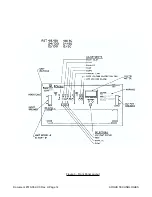
Feed the cable through the selected output hole and route cable as per figure #2. Crimp on the ap-
propriate lugs to the two output lugs. Secure the output cables to the output post of the same polar-
ity. Install the supplied local alarm common wire to the approriate output terminal if a remote alarm
Document #010-002-C0 Rev. H Page 10
ARGUS TECHNOLOGIES
Содержание RST 48/30
Страница 1: ...RST 48 30 Switched Mode Rectifier Eliminator 010 006 B0 ...
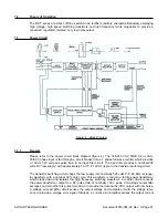
Страница 24: ...Document 010 002 C0 Rev H Page 14 ARGUS TECHNOLOGIES Figure 3 Front Panel Layout ...
Страница 52: ......
Страница 53: ......
Страница 63: ......
Страница 75: ......


