


4.0
Installation Instructions
4.1
Tools Required
Philips screw driver (Tip Size 3/16")
Philips screw driver (Tip Size 1/4")
Slotted screw driver (Blade size 1/4")
Slotted screw driver (Blade size 1/8")
Slotted screw driver (Blade size .09" x .02") or tweaker
4 1/2 Digit Digital Voltmeter
Adjustable resistive load 24/48 volts
4.2
Inspection
All Argus products are shipped in rugged, double walled boxes and are “foamed in place” to mini-
mize shock that may occur during transporting. Packaging assemblies and methods are tested to
National Safe Transit Association standards.
Prior to uncrating, note any damage to the shipping container. Uncrate the rectifier and inspect the
exterior. If any damage is observed, contact the carrier immediately.
Open the front panel of the unit and continue the inspection for any internal damage. In the unlikely
event of internal damage do not operate the unit until Argus Technologies has been contacted for
advice on the impact of any damage.
4.3
Preparation/Mounting
The unit has been designed for mounting in a 19" or 23" EIA standard relay rack. Mounting brack-
ets are universal for 1" or 1 3/4" spacing plus reversible for 19" or 23“ mounting configurations. Indi-
vidual units shipped from the factory are arranged for the 19" mounting configuration. To adapt to
23" mounting, remove the four attaching screws, then flip the brackets so that the large flange is
against the rectifier chassis, then re-attach with mounting screws. The brackets may also be relo-
cated for flush mounting of the unit in a rack. To flush mount the unit, the 19" or 23" orientation
should first be selected then the brackets should be moved to the front mounting position from the
mid mounting (factory) arrangement.
As indicated by the front panel labelling, the unit must be mounted in a clean and dry environment.
Sufficient access to an uninterrupted air source must be provided in front of the unit. Allow at least
two inches of free space behind the unit if two units are stacked directly on top of each other or
three inches if three units are stacked directly on top of each other for ease of access and airflow.
When installed in a relay rack, one extra rack space can be left between units to provide additional
airflow, thereby reducing stress on the unit. If a free space is provided above a unit, space behind
the unit is not required.
The unit should be mounted to the rack using four #12 -24 x 1/2" screws in each bracket. A captive
type of drive such as Philips head is preferred to eliminate the possibility of slippage and scratching
of the unit’s exterior.
ARGUS TECHNOLOGIES
Document #010-002-C0 Rev. H Page 7
Содержание RST 48/30
Страница 1: ...RST 48 30 Switched Mode Rectifier Eliminator 010 006 B0 ...
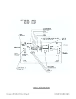
Страница 24: ...Document 010 002 C0 Rev H Page 14 ARGUS TECHNOLOGIES Figure 3 Front Panel Layout ...
Страница 52: ......
Страница 53: ......
Страница 63: ......
Страница 75: ......


