


4.6.2
Float/Equalize (Initial)
Depress the voltmeter display button and observe the output voltage. If this is not the desired “no
load” float voltage re-adjust the level using a tweaker or small screw driver to the desired level. The
output voltage may be monitored via the panel meter or by connecting a D.V.M. (Digital Voltmeter),
e/w miniature banana plugs (.08" probes), to the front output sense test points. Select “Equalize”
mode and adjust the no load equalize voltage if necessary as per the sequence outlined in section
6.3.
4.6.3
Over Voltage Protection (Initial)
Prior to closing the output breaker, the output over voltage protection level should be set to the de-
sired level if different from the factory setting. If a new level is to be set, first increase the OVP con-
trol to the maximum setting. Place the unit in the “Test” mode and then adjust the output via the
“Test” voltage control to the desired trip point. Adjust the OVP alarm control down (coun-
ter-clockwise) until the the OVP trips and the unit shuts down. Reset by turning the input breaker to
the “off” position and then “on” again. The unit will come back up in the “Float” mode.
4.6.4
DC Start-up
Close the output breaker, thereby connecting the unit to the load. If the OVP trips, then the sense
lines have probably been reversed. If so, shut the unit down and correct the polarity of the lines.
The rectifier fail light should extinguish when the unit is providing current above 5% of the rated out-
put or when connected to a battery. The “Power on”, “Float” mode, and possibly the “current limit”
indicators should be the only indicators that are lit. If not, refer to the trouble shooting section of this
manual.
Before closing the output breaker of other units, proceed to section 4.6.5 (paralleling).
4.6.5
Paralleling
When the unit is used in a multi-rectifier configuration the output slope adjustment should be given
a preliminary adjustment so that the rectifiers will share the load. Set the slope controls of all units
to vertical (12 o’clock) position. Assure that the “rectifier fail” indicators of the other units are “on”
then turn on the other units output breakers. Fine tune the slope controls of the unit to get an even
sharing of the load.
ARGUS TECHNOLOGIES
Document #010-002-C0 Rev. H Page 13
Содержание RST 48/30
Страница 1: ...RST 48 30 Switched Mode Rectifier Eliminator 010 006 B0 ...
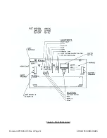
Страница 24: ...Document 010 002 C0 Rev H Page 14 ARGUS TECHNOLOGIES Figure 3 Front Panel Layout ...
Страница 52: ......
Страница 53: ......
Страница 63: ......
Страница 75: ......


