


PiCUS TreeQinetic Manual
29
Furthermore:
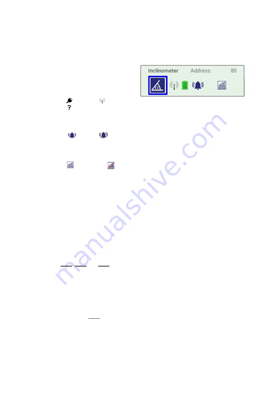
1. Device List
This list shows the sensor modules found, sorted by type. Each list entry displays
different detailed information about the respective device:
a. Device Type (Text)
b. Address
c. Device color
d. Device type (Pictogram)
e. Connection type
Cable
Radio
Could not be found after a new search
f. Battery status
g. Alarm switch
Set whether or not this device may trigger an overload alarm.
Active
Inactive
h. Recording switch
Set whether the measurement data of this device should be recorded, or it
should only appear in the live data display.
Record data
Only live data display, no data recording
If a device is found during a search, the list entry is displayed with a pale green
background color. If the same device is not found during a new search, the list entry
is retained, but is displayed with a grey background color and a
?
instead of the
connection type.
This can have various causes, such as:
•
Interrupted radio connection after change of position of the sensor module or
communication unit
•
Empty battery of the sensor module
•
Sensor module has switched off due to too long inactivity
Additional information is required for the device
type’s forcemeter, elastometer and
inclinometer. The corresponding input pages are opened by tapping on the entries in
the device list.
See
2. List of measurements
Here all measurements which were performed with this test setup are listed. Each list
element shows the name and the time when the measurement was started.
•
Start a new measurement by tapping on the first list entry
Start new
Measurement
→
the view automatically switches to the tab
Measurement
and the page
Control
•
Delete a saved measurement via the context menu of the respective list entry
5.5.4 Page
– Forcemeter
This page is used to enter instrument specific data for each forcemeter.
a.
b.
c.
d.
e.
f.
g.
h.


