Instruction manual – AQ 110 arc protection unit
22 (80
)
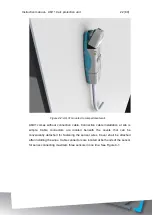
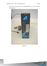
Figure 4-2: AQ 01 mounted to compartment wall.
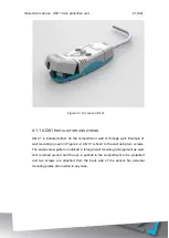
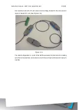
AQ01 comes without connection cable. Connection cable installation at site is
simple. Cable connectors are located beneath the covers that can be
conveniently detached for fastening the sensor wires. Cover shall be attached
after installing the wires. Cable connectors are located at both ends of the sensor
for series connecting maximum three sensors in one line. See Figure 4-1.
Содержание AQ 110 Series
Страница 1: ...INSTRUCTION MANUAL AQ 110 Arc Protection Unit ...
Страница 10: ...Instruction manual AQ 110 arc protection unit 10 80 Figure 2 3 AQ 110F simplified block diagram ...
Страница 60: ...Instruction manual AQ 110 arc protection unit 60 80 7 CONNECTIONS Figure 7 1 AQ 110P terminals at rear plate ...
Страница 61: ...Instruction manual AQ 110 arc protection unit 61 80 Figure 7 2 AQ 110F terminals at rear plate ...
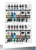
Страница 65: ...Instruction manual AQ 110 arc protection unit 65 80 8 WIRING DIAGRAMS Figure 8 1 AQ 110P Wiring diagram ...
Страница 66: ...Instruction manual AQ 110 arc protection unit 66 80 Figure 8 2 AQ 110F Wiring diagram ...
Страница 68: ...Instruction manual AQ 110 arc protection unit 68 80 Figure 9 2 AQ 110 dimensions in millimeters 3D view ...
Страница 69: ...Instruction manual AQ 110 arc protection unit 69 80 Figure 9 3 AQ 110 cut out for panel mounting millimeters ...
Страница 74: ...Instruction manual AQ 110 arc protection unit 74 80 Tested by Approved by ...


