Instruction manual – AQ 110 arc protection unit
13 (80
)
N/A in AQ
110F
S5
Amber
N/A in AQ
110F
Normal status
Sensor channel
5 activated
N/A in AQ 110F
Fiber sensor
discontinuity or
system set-up
not performed
Check why sensor activated or
check the sensor continuity or
perform system set-up (see
chapter:3.3.1 Auto
BI1
Amber
Normal status
Binary input 1
activated
Binary input 1
loose
connection
Check the binary input wiring.
BI2
Amber
Normal status
Binary input 2
activated
Binary input 2
loose
connection
Check the binary input wiring.
BO1
Amber
Normal status
Binary Output
activated
N/A
IL1
Amber
Normal status,
actual current
below set point
IL1 current
above setpoint
Open CT
connection in
channel IL1
Check the current setpoint
levels or check the CT wiring.
IL2
Amber
Normal status,
actual current
below set point
IL2 current
above setpoint
Open CT
connection in
channel IL2
Check the current setpoint
levels or check the CT wiring.
IL3
Amber
Normal status,
actual current
below set point
IL3 current
above setpoint
Open CT
connection in
channel IL3
Check the current setpoint
levels or check the CT wiring
Io
Amber
Normal status,
actual current
below set point
Residual
current above
setpoint
N/A
Check the residual current
setpoint level
HSO1
Red
Normal status
HSO 1
activated.
N/A
Check the reason for
activation. Clear the fault and
reset indications by pushing
SET button.
HSO2
Red
Normal status
HSO 2
activated.
N/A
Check the reason for
activation. Clear the fault and
reset indications by pushing
SET button.
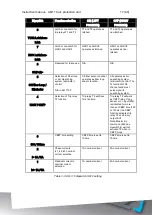
Table 3-1: LED operation quick guide
Содержание AQ 110 Series
Страница 1: ...INSTRUCTION MANUAL AQ 110 Arc Protection Unit ...
Страница 10: ...Instruction manual AQ 110 arc protection unit 10 80 Figure 2 3 AQ 110F simplified block diagram ...
Страница 60: ...Instruction manual AQ 110 arc protection unit 60 80 7 CONNECTIONS Figure 7 1 AQ 110P terminals at rear plate ...
Страница 61: ...Instruction manual AQ 110 arc protection unit 61 80 Figure 7 2 AQ 110F terminals at rear plate ...
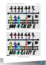
Страница 65: ...Instruction manual AQ 110 arc protection unit 65 80 8 WIRING DIAGRAMS Figure 8 1 AQ 110P Wiring diagram ...
Страница 66: ...Instruction manual AQ 110 arc protection unit 66 80 Figure 8 2 AQ 110F Wiring diagram ...
Страница 68: ...Instruction manual AQ 110 arc protection unit 68 80 Figure 9 2 AQ 110 dimensions in millimeters 3D view ...
Страница 69: ...Instruction manual AQ 110 arc protection unit 69 80 Figure 9 3 AQ 110 cut out for panel mounting millimeters ...
Страница 74: ...Instruction manual AQ 110 arc protection unit 74 80 Tested by Approved by ...


