Instruction manual – AQ 110 arc protection unit
64 (80
)
configured to control the arc quenching system (eliminator. In this case Tx shall
be utilized to control the arc quenching system. The unit is sending a continuous
light pulse to arc quenching system for self-supervision purposes.
AQ 110F version has 3 arc fiber loop sensor channels (S1, S2, S3) with
transceiver and receiver (Tx, Rx) in each channel. Additionally one transceiver
(Tx) is available for arc quenching system (eliminator) control.
For details on sensors refer to chapter 4 Arc Sensors.
7.2.3
B
INARY INPUTS
BI1
AND
BI2
AQ 110 contains two binary inputs. The function of binary inputs is selected using
dipswitches according to SAS applications (see chapter 3.6). Typically binary
inputs are utilized for receiving the arc light information from AQ 101 and AQ 102
units and receiving the overcurrent information from other AQ 110 devices.
The inputs are activated by connecting a dc signal exceeding the specified
nominal threshold level of the corresponding input. There are three different
nominal threshold levels available, 24 or 110 or 220 Vdc. The desired threshold
value has to be specified when ordering. The actual activation of the binary input
occurs at 80% of the specified nominal threshold value (i.e. 19 Vdc, 88 Vdc or
176 Vdc).
7.3
A
UXILIARY VOLTAGE
The auxiliary power supply voltage is 80….265Vac/dc. Optionally a 24…72Vdc
version is available.
After powering up the unit protection is active and operational within 50ms.
Содержание AQ 110 Series
Страница 1: ...INSTRUCTION MANUAL AQ 110 Arc Protection Unit ...
Страница 10: ...Instruction manual AQ 110 arc protection unit 10 80 Figure 2 3 AQ 110F simplified block diagram ...
Страница 60: ...Instruction manual AQ 110 arc protection unit 60 80 7 CONNECTIONS Figure 7 1 AQ 110P terminals at rear plate ...
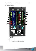
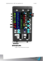
Страница 61: ...Instruction manual AQ 110 arc protection unit 61 80 Figure 7 2 AQ 110F terminals at rear plate ...
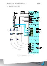
Страница 65: ...Instruction manual AQ 110 arc protection unit 65 80 8 WIRING DIAGRAMS Figure 8 1 AQ 110P Wiring diagram ...
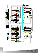
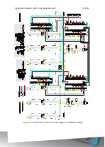
Страница 66: ...Instruction manual AQ 110 arc protection unit 66 80 Figure 8 2 AQ 110F Wiring diagram ...
Страница 68: ...Instruction manual AQ 110 arc protection unit 68 80 Figure 9 2 AQ 110 dimensions in millimeters 3D view ...
Страница 69: ...Instruction manual AQ 110 arc protection unit 69 80 Figure 9 3 AQ 110 cut out for panel mounting millimeters ...
Страница 74: ...Instruction manual AQ 110 arc protection unit 74 80 Tested by Approved by ...

