Instruction manual – AQ 110 arc protection unit
12 (80
)
power supply loss the actual LED status can be visualized from the front of the
unit.
3.2
LED
OPERATION
QUICK
GUIDE
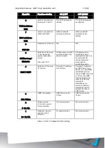
The table below describes the function of each indicator LED in front of the AQ
110 unit. Note that the use of sensor channels differs between AQ 110P and AQ
110F versions. Sensor channels S4 and S5 are not in use in AQ 110F version.
LED
OFF
STEADY
ON
BLINKING
ACTION IF ABNORMAL
POWER
Blue
Auxiliary
supply
disconnected
Auxiliary power
connected
N/A
Check the power source
ERROR
Red
System
healthy
System failure
Configuration
mismatch.
Protection partly
operational
Verify system condition. see
chapters 11: Troubleshooting
guide and 5: System self-
T1
Red
Normal status
Trip relay T1
activated
N/A
Check the reason for trip.
Clear the fault and reset
indications by pushing SET
button
T2
Red
Normal status
Trip relay T2
activated
N/A
Check the reason for trip.
Clear the fault and reset
indications by pushing SET
button
T3
Red
Normal status
Trip relay T3
activated
N/A
Check the reason for trip.
Clear the fault and reset
indications by pushing SET
button
T4
Red
Normal status
Trip relay T4
activated
N/A
Check the reason for trip.
Clear the fault and reset
indications by pushing SET
button
S1
Amber
Normal status
Sensor channel
1 activated
Sensor channel
1 discontinuity
or system set-
up not
performed
Check why sensor activated or
check the sensor continuity or
perform system set-up (see
chapter:3.3.1 Auto
S2
Amber
Normal status
Sensor channel
2 activated
Sensor channel
discontinuity or
system set-up
not performed
Check why sensor activated or
check the sensor continuity or
perform system set-up (see
chapter:3.3.1 Auto
S3
Amber
Normal status
Sensor channel
3 activated
Sensor channel
3 discontinuity
or system set-up
not performed
Check why sensor activated or
check the sensor continuity or
perform system set-up (see
chapter:3.3.1 Auto
S4
Amber
Normal status
Sensor channel
4 activated
N/A in AQ 110F
Sensor channel
4 discontinuity
or system set-up
not performed
Check why sensor activated or
check the sensor continuity or
perform system set-up (see
chapter:3.3.1 Auto
Содержание AQ 110 Series
Страница 1: ...INSTRUCTION MANUAL AQ 110 Arc Protection Unit ...
Страница 10: ...Instruction manual AQ 110 arc protection unit 10 80 Figure 2 3 AQ 110F simplified block diagram ...
Страница 60: ...Instruction manual AQ 110 arc protection unit 60 80 7 CONNECTIONS Figure 7 1 AQ 110P terminals at rear plate ...
Страница 61: ...Instruction manual AQ 110 arc protection unit 61 80 Figure 7 2 AQ 110F terminals at rear plate ...
Страница 65: ...Instruction manual AQ 110 arc protection unit 65 80 8 WIRING DIAGRAMS Figure 8 1 AQ 110P Wiring diagram ...
Страница 66: ...Instruction manual AQ 110 arc protection unit 66 80 Figure 8 2 AQ 110F Wiring diagram ...
Страница 68: ...Instruction manual AQ 110 arc protection unit 68 80 Figure 9 2 AQ 110 dimensions in millimeters 3D view ...
Страница 69: ...Instruction manual AQ 110 arc protection unit 69 80 Figure 9 3 AQ 110 cut out for panel mounting millimeters ...
Страница 74: ...Instruction manual AQ 110 arc protection unit 74 80 Tested by Approved by ...


