Instruction manual – AQ 110 arc protection unit
52 (80
)
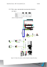
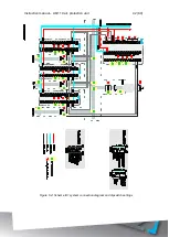
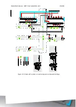
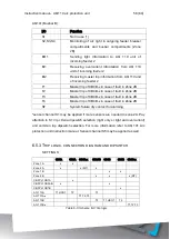
6.4.3
T
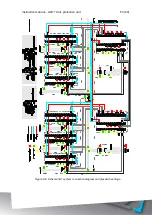
RIP LOGIC
,
CONNECTION DIAGRAM AND DIPSWITCH
SETTINGS
CB1A
CB2A
CB4A-x CB3AB CB1B
CB2B
CB4B-x
Zone 1A
x
x
Zone 2A
x
x (MT)
x
Zone 3A
x
Zone 1B
x
x
Zone 2B
x
x
x (MT)
Zone 3B
x
CBFP of CB1A
x
CBFP of CB4A-x
x
x
CBFP of CB3AB
x
x
CBFP of CB1B
x
CBFP of CB4B-x
x
x
AQ 110A
T1
T2
T3
AQ 101A-x
T1
AQ 110B
T3
T1
T2
AQ 101B-x
T1
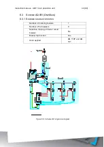
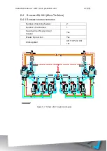
Table 6-4: Scheme IIA1 trip logic
Содержание AQ 110 Series
Страница 1: ...INSTRUCTION MANUAL AQ 110 Arc Protection Unit ...
Страница 10: ...Instruction manual AQ 110 arc protection unit 10 80 Figure 2 3 AQ 110F simplified block diagram ...
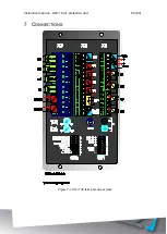
Страница 60: ...Instruction manual AQ 110 arc protection unit 60 80 7 CONNECTIONS Figure 7 1 AQ 110P terminals at rear plate ...
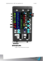
Страница 61: ...Instruction manual AQ 110 arc protection unit 61 80 Figure 7 2 AQ 110F terminals at rear plate ...
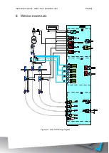
Страница 65: ...Instruction manual AQ 110 arc protection unit 65 80 8 WIRING DIAGRAMS Figure 8 1 AQ 110P Wiring diagram ...
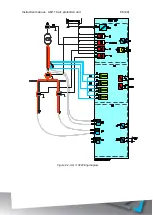
Страница 66: ...Instruction manual AQ 110 arc protection unit 66 80 Figure 8 2 AQ 110F Wiring diagram ...
Страница 68: ...Instruction manual AQ 110 arc protection unit 68 80 Figure 9 2 AQ 110 dimensions in millimeters 3D view ...
Страница 69: ...Instruction manual AQ 110 arc protection unit 69 80 Figure 9 3 AQ 110 cut out for panel mounting millimeters ...
Страница 74: ...Instruction manual AQ 110 arc protection unit 74 80 Tested by Approved by ...

