Instruction manual – AQ 110 arc protection unit
70 (80
)
10
T
ESTING
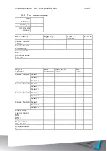
It is recommended that the AQ 110 unit is tested prior to substation energizing.
Testing is carried out by simulating arc light to each sensor and verifying the
tripping and LED indication. For arc light simulation, use a superior camera flash
type: Canon Speedlite 430EX
or equivalent. For testing of non-latched signals
and CBFP function use Mini Maglite 2 CELL AAA or equivalent type of flashlight.
Check that camera flash or flashlight has fully charged battery when testing.
10.1
C
ARRYING OUT TESTING IN LIGHT ONLY MODE
1)
Check that the dipswitch setting positions are in accordance to your
application
2)
Activate the camera flash within 20cm (12 inches) of the AQ01 sensor
unit or AQ07 fiber loop sensor if in use.
3)
Verify that the corresponding sensor channel indication LED status is
changed to ON.
4)
Verify the relay output(s) activation(s) by checking the circuit breaker
status or by monitoring trip contact status. The circuit breaker should
open or contacts operate. Note: A best practice is to operate the
circuit breaker at testing.
5)
Verify that the corresponding relay output(s) LED(s) indication status
is changed to ON
6)
If binary output (BO1) or high speed output (HSO) signal is utilized
verify the BO1 or HSO signal activation by status change of relevant
input where the output signal is connected or by measuring the signal
output voltage. Note that BO1 signal is a non-latched type.
7)
If binary output or high speed output (HSO) signal is utilized verify
that BO1 LED or relevant HSO LED is lit.
8)
Press SET push-button to reset all indications and latches.
9)
If binary input BI2 is utilized for master trip activate the corresponding
binary input and verify that trip has occurred by repeating 4 and 5.
10)
Press SET push-button to reset all indications and latches.
11)
Repeat the testing procedure for all sensors.
Содержание AQ 110 Series
Страница 1: ...INSTRUCTION MANUAL AQ 110 Arc Protection Unit ...
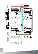
Страница 10: ...Instruction manual AQ 110 arc protection unit 10 80 Figure 2 3 AQ 110F simplified block diagram ...
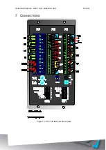
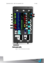
Страница 60: ...Instruction manual AQ 110 arc protection unit 60 80 7 CONNECTIONS Figure 7 1 AQ 110P terminals at rear plate ...
Страница 61: ...Instruction manual AQ 110 arc protection unit 61 80 Figure 7 2 AQ 110F terminals at rear plate ...
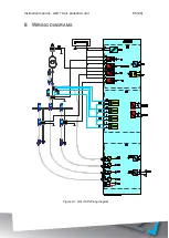
Страница 65: ...Instruction manual AQ 110 arc protection unit 65 80 8 WIRING DIAGRAMS Figure 8 1 AQ 110P Wiring diagram ...
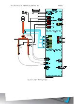
Страница 66: ...Instruction manual AQ 110 arc protection unit 66 80 Figure 8 2 AQ 110F Wiring diagram ...
Страница 68: ...Instruction manual AQ 110 arc protection unit 68 80 Figure 9 2 AQ 110 dimensions in millimeters 3D view ...
Страница 69: ...Instruction manual AQ 110 arc protection unit 69 80 Figure 9 3 AQ 110 cut out for panel mounting millimeters ...
Страница 74: ...Instruction manual AQ 110 arc protection unit 74 80 Tested by Approved by ...

