Instruction manual – AQ 110 arc protection unit
17 (80
)
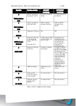
Dipswitch
Function selection
ON (LEFT
POSITION)
OFF (RIGHT
POSITION)
8
T1/T2 Latch/non-
latch
Latch or non-latch for
trip relays T1 and T2
T1 and T2 operate as
latched.
T1 and T2 operate as
non-latched.
7
HSO Latch/non-
latch
Latch or non-latch for
HSO1 and HSO2
HSO1 and HSO2
operates as latched.
HSO1 and HSO2
operates as non-
latched.
6
S1:P>/L>
Reserved for future use N/A
N/A
5
S5:Fiber Loop /
Eliminator
Selection of Fiber loop
or Arc Quenching
system (eliminator)
control
N/A in AQ 110F
S5 fiber sensor channel
operates as fiber loop
sensor function.
S5 operates as arc
quenching system
(eliminator) control. The
Tx terminal of S5
channel sends test
pulse signal to
quenching system.
4
FAST / CBFP
Selection of Trip relay
T2 function
Trip relay T2 will have
7ms trip time.
Trip relay T2 will work
as CBFP relay. If any
sensor or L> input (BI2)
is activated for more
than set CBFP time (100
or 150ms) the CBFP
function activates trip
relay T2 and binary
output BO1.
Note: Master trip
command (BI2, see
dipswitch 4) will not
activate T2 when in
CBFP mode.
3
100 / 150ms
CBFP time setting
CBFP time is set to
100ms.
CBFP time is set to
150ms.
2
I> 1A / 5A
Phase currents
IL1,IL2,IL3 nominal
current selection
1A nominal current
5A nominal current
1
Io> 1A / 5A
Residual current Io
nominal current
selection
1A nominal current
5A nominal current
Table 3-3: AQ 110 dipswitch SW 2 setting
Содержание AQ 110 Series
Страница 1: ...INSTRUCTION MANUAL AQ 110 Arc Protection Unit ...
Страница 10: ...Instruction manual AQ 110 arc protection unit 10 80 Figure 2 3 AQ 110F simplified block diagram ...
Страница 60: ...Instruction manual AQ 110 arc protection unit 60 80 7 CONNECTIONS Figure 7 1 AQ 110P terminals at rear plate ...
Страница 61: ...Instruction manual AQ 110 arc protection unit 61 80 Figure 7 2 AQ 110F terminals at rear plate ...
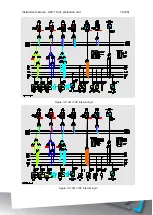
Страница 65: ...Instruction manual AQ 110 arc protection unit 65 80 8 WIRING DIAGRAMS Figure 8 1 AQ 110P Wiring diagram ...
Страница 66: ...Instruction manual AQ 110 arc protection unit 66 80 Figure 8 2 AQ 110F Wiring diagram ...
Страница 68: ...Instruction manual AQ 110 arc protection unit 68 80 Figure 9 2 AQ 110 dimensions in millimeters 3D view ...
Страница 69: ...Instruction manual AQ 110 arc protection unit 69 80 Figure 9 3 AQ 110 cut out for panel mounting millimeters ...
Страница 74: ...Instruction manual AQ 110 arc protection unit 74 80 Tested by Approved by ...


