Instruction manual – AQ 110 arc protection unit
34 (80
)
5
S
YSTEM SELF
-
SUPERVISION
AQ 110 includes extensive self-supervision feature. Self-supervision includes
both internal functions and external connections. The self-supervision module
monitors power supply, HW and SW malfunctions and binary input connection
and sensor problems. CT circuit is monitored as well and an open circuit will
cause an alarm. Dipswitch settings are also supervised by comparing actual
value with stored Non-volatile memory data (see chapter 3.3.1 Auto configuration
(system setup)).
In a healthy condition the power LED is on and the Self-supervision (SF) relay is
energized. If the self-supervision function detects a faulty condition the self-
supervision relay is released and the ERROR LED is lit.
If a sensor failure occurs, the unit will go into ERROR-mode. The error LED will
turn on, the SF relay will release and the corresponding faulty sensor channel
LED will start blinking. In this situation the unit is still in protection mode, but with
the faulty sensor channel blocked. If the error is resolved the unit will
automatically clear the SF-status. This means that SF-relay will energize and the
error led will turn off. If one or more of the sensors are disconnected the healthy
sensors remain in use and unit remains operational accordingly. The AQ 110 will
remain in error mode until the disconnected sensors are repaired.
If a dip switch setting is changed after the auto-configuration function (see
chapter 3.3.1 Auto configuration) has been executed, the unit will go into SF-
alarm mode. The configured (stored) setting is however still valid and the unit is
still operational.
5.1
O
PEN
CT
MONITORING
If there is a current flow of more than 0.2xIn the unit assumes that the switchgear
is energized. In this case phases IL1, IL2 and IL3 are monitored and supervised
for open connection (no current flow).
If one or two of the three phases is 0 while the other(s) remain above 0.2xIn the
unit will issue an open CT alarm.
When CT open alarm is issued, SF-relay is released, Error LED turned on and
corresponding IL1>, IL2>, IL3 LED starts blinking.
Содержание AQ 110 Series
Страница 1: ...INSTRUCTION MANUAL AQ 110 Arc Protection Unit ...
Страница 10: ...Instruction manual AQ 110 arc protection unit 10 80 Figure 2 3 AQ 110F simplified block diagram ...
Страница 60: ...Instruction manual AQ 110 arc protection unit 60 80 7 CONNECTIONS Figure 7 1 AQ 110P terminals at rear plate ...
Страница 61: ...Instruction manual AQ 110 arc protection unit 61 80 Figure 7 2 AQ 110F terminals at rear plate ...
Страница 65: ...Instruction manual AQ 110 arc protection unit 65 80 8 WIRING DIAGRAMS Figure 8 1 AQ 110P Wiring diagram ...
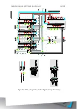
Страница 66: ...Instruction manual AQ 110 arc protection unit 66 80 Figure 8 2 AQ 110F Wiring diagram ...
Страница 68: ...Instruction manual AQ 110 arc protection unit 68 80 Figure 9 2 AQ 110 dimensions in millimeters 3D view ...
Страница 69: ...Instruction manual AQ 110 arc protection unit 69 80 Figure 9 3 AQ 110 cut out for panel mounting millimeters ...
Страница 74: ...Instruction manual AQ 110 arc protection unit 74 80 Tested by Approved by ...

