180
Options List
Term
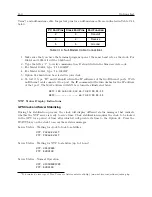
) and null-modem cable. Important pins for a null-modem cable are indicated in Table C.14
below.
PC Port Pins
Clock Port Pins
Port Function
2
3
Transmit
3
2
Receive
5
5
Ground
Table C.14: Null-Modem Cable Connections
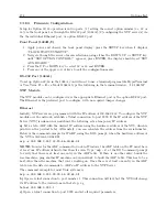
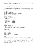
1. Make sure that you have the terminal program open at the same baud rate as the clock. For
1084A and 1093A it will be 9600 baud.
2. Type the letter “v” to verify communication. It should return the firmware date code.
3. For Model 1084A, type “1,11,1084XI”.
4. For Model 1093A, type “1,8,1093XI”.
5. Option 34 should now be selected in your clock.
6. To test it, type “IP” and it should return the IP addresses of the two Ethernet ports. With
no Ethernet cable connected to a port, the IP command will return dashes for the IP address
of that port. The MAC address will still be returned as illustrated below.
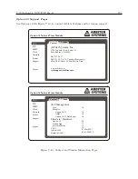
NET1:192.168.000.232 64:73:E2:XX:XX:XX
NET2:---.---.---.--- 64:73:E2:XX:XX:XX
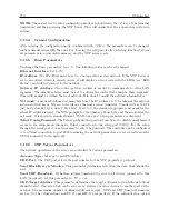
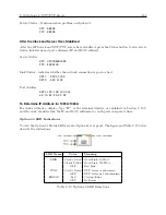
NTP Status Display Indications
GPS Clock and Server Stabilizing
During the stabilization process, the clock will display different status messages that indicate
whether the NTP server is ready to serve time. Clock stabilization requires the clock to be locked
to the GPS for a period of time after which it will provide its time to the Option 34. Press the
STATUS key on the clock to access these status messages.
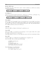
Server Status – Waiting for clock to lock to satellites
NTP: PLEASE WAIT...
PTP: PLEASE WAIT
Server Status – Waiting for NTP to stabilize (up to 1 hour)
NTP: UNLOCKED
PTP: RUNNING
Server Status – Normal Operation
NTP: SYNCHRONIZED
PTP: RUNNING
3
To download a free copy of Tera Term, see Arbiter website at http://www.arbiter.com/software/index.php.
Содержание 1084A
Страница 4: ...iv ...
Страница 6: ...vi ...
Страница 18: ...xviii LIST OF FIGURES ...
Страница 23: ...1 4 Attaching Rack Mount Ears to 1084A B C Series Clocks 3 Figure 1 2 Attaching Rack Mount Ears ...
Страница 24: ...4 Unpacking the Clock ...
Страница 36: ...16 Connecting Inlet Power Input and Output Signals ...
Страница 39: ...4 1 GPS Antenna Installation 19 Figure 4 2 Antenna Mounting Bracket Figure 4 3 Antenna Mounting with AS0044600 ...
Страница 44: ...24 GPS Antenna and Cable Information ...
Страница 114: ...94 Startup and Basic Operation ...
Страница 123: ...B 4 Physical Dimensions 103 Figure B 1 Suggested Mounting of the AS0094500 Surge Arrester ...
Страница 124: ...104 Using Surge Arresters ...
Страница 134: ...114 Options List C 6 2 Option 06 Firmware Setup Figure C 3 Option 06 Firmware Setup ...
Страница 142: ...122 Options List Figure C 5 Option 06 Output Jumper Settings ...
Страница 143: ...C 6 Option 06 Parallel BCD Output 1 millisecond Resolution 123 Figure C 6 Option 06 Board Layout and Jumper Locations ...
Страница 157: ...C 10 Option 17 Parallel BCD Output and Second RS 232C Port 137 Figure C 12 Option 17 Output Jumper Settings ...
Страница 158: ...138 Options List Figure C 13 Option 17 Board Layout and Jumper Locations ...
Страница 163: ...C 13 Option 20A Four Fiber Optic Outputs 143 Figure C 14 Option 20A Jumper Locations ...
Страница 170: ...150 Options List Figure C 16 Option 23 Internal Jumper Setup ...
Страница 172: ...152 Options List Figure C 17 Option 27 Jumper Locations ...
Страница 190: ...170 Options List Figure C 20 Option 29 Connector Signal Locations ...
Страница 246: ...226 Options List ...


