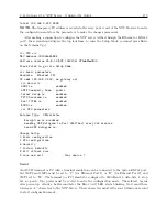
C.17 Option 29: Four Additional Outputs; Dry Contacts; +25/50 Vdc
167
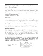
Solid State Relay Output, continued
Power Supply:
Individually configurable for 0 VDC, +25 VDC, or +50 VDC.
Available Signals:
1 PPH, 1 PPM, 1 PPS, Programmable Pulse, Locked and
Out of Lock.
Pulse Width:
Individually configurable for a fixed, 50-ms pulse, or the de-
fault width of pulse provided by the clock mainframe.
Available
Configurations:
1. Dry contact closure.
2. Contact closure to ground.
3. +25/50 VDC switched for grounded load
4.
+25/50 VDC with contact closure to ground for non-
grounded load.
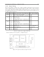
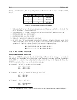
See Table C.11: Operating Modes of SSR Outputs.
Mode
SSR Output 1
SSR Output 2
Dry Contact Closure
Connect load to pins 10 & 11
(polarity not important)
Connect load to pins 14 & 15
(polarity not important)
Contact Closure to Ground
Short pins 9 & 10, connect
load to pin 11
Short pins 13 & 14, connect
load to pin 15
+25/50 VDC Switched
to Grounded Load
Short pins 11 & 12, connect
load to pins 9 (
−
) & 10 (+)
Short pins 15 & 16, connect
load to pins 13 (
−
) & 14 (+)
+25/50 VDC Switched
to Floating Load
Short pins 9 & 10, connect
load to pins 11 (
−
) & 12 (+)
Short pins 13 & 14, connect
load to pins 15 (
−
) & 16 (+)
Table C.11: Option 29, Operating Modes of SSR Outputs
Содержание 1084A
Страница 4: ...iv ...
Страница 6: ...vi ...
Страница 18: ...xviii LIST OF FIGURES ...
Страница 23: ...1 4 Attaching Rack Mount Ears to 1084A B C Series Clocks 3 Figure 1 2 Attaching Rack Mount Ears ...
Страница 24: ...4 Unpacking the Clock ...
Страница 36: ...16 Connecting Inlet Power Input and Output Signals ...
Страница 39: ...4 1 GPS Antenna Installation 19 Figure 4 2 Antenna Mounting Bracket Figure 4 3 Antenna Mounting with AS0044600 ...
Страница 44: ...24 GPS Antenna and Cable Information ...
Страница 114: ...94 Startup and Basic Operation ...
Страница 123: ...B 4 Physical Dimensions 103 Figure B 1 Suggested Mounting of the AS0094500 Surge Arrester ...
Страница 124: ...104 Using Surge Arresters ...
Страница 134: ...114 Options List C 6 2 Option 06 Firmware Setup Figure C 3 Option 06 Firmware Setup ...
Страница 142: ...122 Options List Figure C 5 Option 06 Output Jumper Settings ...
Страница 143: ...C 6 Option 06 Parallel BCD Output 1 millisecond Resolution 123 Figure C 6 Option 06 Board Layout and Jumper Locations ...
Страница 157: ...C 10 Option 17 Parallel BCD Output and Second RS 232C Port 137 Figure C 12 Option 17 Output Jumper Settings ...
Страница 158: ...138 Options List Figure C 13 Option 17 Board Layout and Jumper Locations ...
Страница 163: ...C 13 Option 20A Four Fiber Optic Outputs 143 Figure C 14 Option 20A Jumper Locations ...
Страница 170: ...150 Options List Figure C 16 Option 23 Internal Jumper Setup ...
Страница 172: ...152 Options List Figure C 17 Option 27 Jumper Locations ...
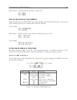
Страница 190: ...170 Options List Figure C 20 Option 29 Connector Signal Locations ...
Страница 246: ...226 Options List ...


