background image


16

Installation guide page 1 


 Attention!


The already assembled membranes can be stored for approx. 5 months in the sealed 
pressure tube, preferably cool, but preferably not above 20 ° ambient temperature. 
However, we recommend installing and using the Watermaker as soon as possible. 


 Warning!


Hose connections below the water line should secured with 2 hose clamps. 
All hose clamps must check time to time and tighten if need. 
During assembly of the hose nozzles and fittings, few windings of Teflon-tape have to be 
wrapped around the screw thread against screw direction as tightly as possible. The 
fittings may not be screwed too tightly in the filters or valves.


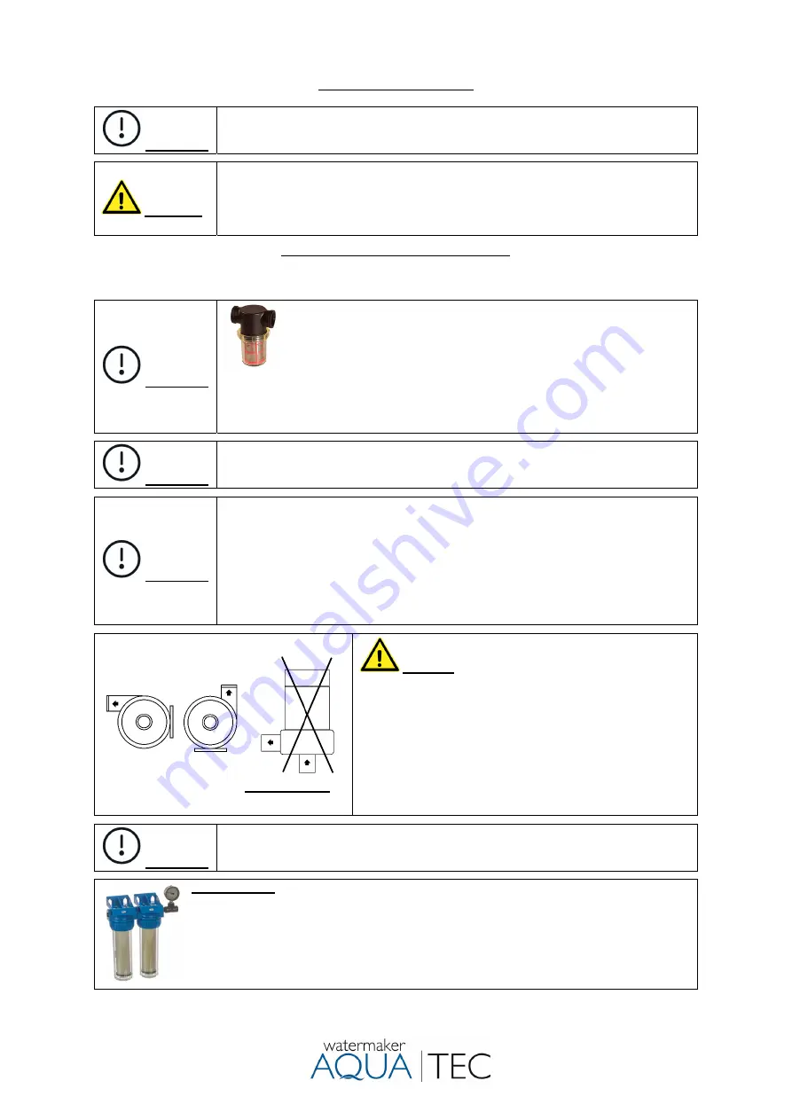
Thru-hull fitting, Strainer and feed pump 


Install a thru-hull fitting and sea-cock, preferably deep under water line. The best place is about mid-ships behind 
the keel. Install strainer and feed pump close as possibly to the sea-cock. 


 Attention!


To avoid mechanical stress, do not mount the strainer directly to the sea-
cock. The thru-hull fitting, coarse filter and the feed pump have to be located 
in an area that will always be under the waterline when the boat is used under 
normal running conditions. 

In order to avoid accumulation of air,

 if possible, install hoses 

moved upward from the thru-hull fitting to the filters and up to the high-pressure pump.  
From the sea-cock outlet to the feed pump inlet, the installation must be horizontal or 
better rising. In order to stay as deep as possible below the waterline, a 90 ° hose nozzle 
at the sea-cock outlet can be helpful.


 Attention!


Avoid connecting to an existing inlet e.g. Main machine air conditioning. Common 
operation is usually not possible because the existing hose cross-sections prevents 
sufficient inflow.


 Attention!


The feed pump is not self-priming and must be flooded before switching on, otherwise 
the bearing will be destroyed by dryness.  
To allow air to escape, switch the pump on and off several times and, if necessary, open 
the vent valves on the prefilter.  
If necessary, remove the high-pressure hose to the membrane at the high-pressure pump 
and close it again after the water has escaped while the feed pump is running. This also 
ensures that the HP pump is filled with water.  
The system can also be vented by flushing with fresh water. 
If necessary, refer to the further notes under Troubleshooting.


Mounting position of the feed pump 


      OK           OK


  not permitted  


Warning!

 Do not connect the feed pump directly to a 

filter housing, tap or similar (risk of breakage).


Only connect to other components with the enclosed hose 
nozzles and hose. The following installation position must be 
observed in order to make it difficult to set deposits and to 
allow the escape of air. 
 
Permissible system pressure fresh water flush: 
Feed pump 

MD 40, 

115 or 230V, 2 bar (29 psi). 

Feed pump 

B-C20/A, 

400 or 440V, 3.5 bar (50 psi) 

(If necessary, install a pressure reducer.)


 Attention!


Depending on the used thru-hull fitting, hull shape and speed, the inflow of seawater can 
be hampered or even be impossible. Damages to the plant due to insufficient or missing 
seawater inflow will not be covered by the warranty or guarantee. 


Filter housing: 


For a good sealing of the filter housing, please lubricate the O-rings in the filter bowls with 
acid-free silicone grease. 
Mount the filter housing at an easily accessible place. Connect the filter inlet with the outlet of 
the feed pump and the filter outlet via PVC hose with the high-pressure pump. Secure all hose 
connections with stainless steel hose clamps. Install all hose connections in a way that air 
accumulations are avoided. 


Содержание Watermaker AC 110

Страница 1: ...cture and distribution by North Marine Handels GmbH Papenreye 61 D 22453 Hamburg Contact sup aquatec watermaker de Tel 49 0 40 36850306 Web www aquatec watermaker de All contents of this manual in par...

Страница 2: ...ent 1 filter housing with holder incl 1 piece carbon filter for fresh water rinsing 2 filter housings with holder incl 1 piece 5 and 20 micron filter pre pressure gauge 2 pcs ball valves 2 way No 1 an...

Страница 3: ...rmitted with clean seawater Warning Never operate your Aquatec Watermaker unsupervised and leave the operation only to trained persons Please note If there are any leaks the boat can fill up with wate...

Страница 4: ...ecification dimensions Recommendation for using your Aquatec reverse osmosis system Daily use is preferable to a one time weekly use The system produces water with a neutral taste and very good qualit...

Страница 5: ...motic pressure is around 30 bar The described process however is reversible by exposing the liquid on the seawater side to mechanical pressure At a pressure of 30 bar the osmotic process cannot take p...

Страница 6: ...n three way valve no 2 to position test outlet 4 Switch on the feed pump The gauge no 9 pressure feed water must show positive pressure De aerate the pre filter system if necessary and control the dra...

Страница 7: ...f the seawater and the age of the R O membrane The data regarding the fresh water production apply to a salinity of 35 grams litre at a temperature of 25 Celsius 77 Fahrenheit at the new membrane A di...

Страница 8: ...on the board side performance of the fresh water pump and the condition of the membranes and therefore cannot be stated on factory side Please find out the required amount of flushing water by discha...

Страница 9: ...iagram fresh water flush Note Flushing working pressure 0 bar 5 Pressure regulation valve 6 Flowmeter product water 7 ships fresh water pump 8 Feed pump 9 Gauge feed pressure 10 Seacock not scope of d...

Страница 10: ...cleaning chemical gets into your fresh water tank Note Working pressure 0 bar 1 Close the sea water intake valve 2 The pressure control valve must be open Turn the product water three way valve no 2...

Страница 11: ...drain the all the water from the pump which is important if there is a risk of frost if possible it is also preferable to blow pressurized air through it in the direction of flow for this purpose rem...

Страница 12: ...egative pressure do not close the cap tightly Since there are about 1 5 litre of water already in each membrane and 1 litre of water in each filter please add the according amount of chemical to the w...

Страница 13: ...13 Memos...

Страница 14: ...5 Pressure regulation valve 6 Flowmeter product water 7 ships fresh water pump 8 Feed pump 9 Gauge feed pressure 10 Seacock not scope of delivery Hose dimensions inner diameter see specification Flow...

Страница 15: ...15 Flow diagram AC 190 Flow diagram AC 240...

Страница 16: ...cross sections prevents sufficient inflow Attention The feed pump is not self priming and must be flooded before switching on otherwise the bearing will be destroyed by dryness To allow air to escape...

Страница 17: ...d inspection work as comfortable as possible Attention After mounting exchange the upper red plastic screw in the crankcase for the dipstick with ventilation Membrane housing pressure vessel For the i...

Страница 18: ...de of the hose with a lubricant e g Dishwashing liquid 3 Screw the sleeve nut anti clockwise onto the hose Leave a distance of 2 mm between the hose and the inner shoulder of the sleeve nut to allow t...

Страница 19: ...ssure hose connections are self sealing by pre assembled O rings Attention Only use cylindrical tread fittings BSP in the plastic end caps of the pressure vessel Taper threads may cause cracks 1 2 3 4...

Страница 20: ...the fitting With the collet held in this position the tube can be removed Attention In order to avoid unnecessary back pressure in the product water line in systems AC 135 to AC 240 only use the blue...

Страница 21: ...1 400 Volt 50 Hz 3 G 1 5 mm AWG 15 From junction box to the motor high pressure pump From board s main distribution to junction box From junction box to the motor of high pressure pump AC 65 AC 110 23...

Страница 22: ...al circuit diagram Aquatec AC 65 up to AC 240 Single phase 230 50 Hz 115 Volt 60 Hz 2 pole motor protection switch Aquatec AC 65 up to AC 240 Single phase 230 5Hz or 115 Volt 60 Hz 3 pole motor protec...

Страница 23: ...al circuit diagram Aquatec AC 150 bis AC 240 HP pump feed pump 3 phase 208 230 400 440 Volt 50 60 Hz Aquatec AC 150 up to AC 240 HP pump 3 phase 208 230 400 440 Volt 50 60 Hz Feed pump 1 phase 230 Vol...

Страница 24: ...Hexagon socket 8 mm under the crankcase Sealed of copper ring Alternatively the oil can be extracted through the oil dipstick opening using a suction pump Dipstick full screwed into crankcase Oil lev...

Страница 25: ...off the screws M6x20 at both ends of the AQUATEC pressure vessel Screw tightening torque for the holding clips 3 Nm Then take off the stainless steel holding clamps Push the end caps in a little befo...

Страница 26: ...dirt Which of the 6 valves causes a problem cannot be seen from the outside The upper 3 pressure valves rarely cause problems As a rule it affects one of the 3 lower suction valves To rectify the faul...

Страница 27: ...valve No 4 to operate toward the 5 or 10 liter conservation tank 4 Alternatively pipe seawater concentrates into a bucket to measure the quantity 5 Using a stop watch to measure the time until filling...

Страница 28: ...ze metal free for stainless steel to prevent seizing Screw No 16C secure with Loctite 243 Tightening torque 22 5 Nm 16C 16A 16D 16B 17 1 12A 9 8 7 4 3 3A 6 6A 2 5 15 13 14 12B 11 6A 10 16E 16F 32 23A...

Страница 29: ...AC 150 115 1 60 und 440 3 60 1 13 141627 Crankshaft AC 150 400 3 50 1 13 141628 Crankshaft AC 150 240 230 1 50 AC 190 240 400 3 50 1 14 141629 Fitting Key 1 15 141630 Connecting Rod 3 16 141631 Plunge...

Страница 30: ...Nm Pump head Type 2 Note Grease the thread of the valve screws No 10 with e g Anti Size metal free for stainless steel to prevent seizing Nut no 35 secure with Loctite 2701 No 52 replaced no 13 14 Aft...

Страница 31: ...older ss 18 mm Typ AC75 135 AC KC 150 190 240 15 141494 O Ring 55 56x3 53 NBR70 1 141495 O Ring 56 82x2 62 NBR70 after 2018 41 141501 O Ring 28 3 x 1 78 NBR 70 Kit 110 3 16 141474 Bearing 2 42 141517...

Страница 32: ...erine Tolerance less than 0 1 ppm Seawater temperature range 4 bis 38 Celsius Water production at 3 5 salinity 25 C and 55 bar pressure AC 75 75 litres hour AC 135 135 litres hour Power requirement hi...

Страница 33: ...ctite 2701 Hose dimensions Hose dimensions inner diameter AC 65 110 AC 75 up to AC 240 From thru hull fitting up to feed pump 5 8 16 mm 3 4 19 mm From feed pump up to sedimentfilter 20 5mic 1 2 13 mm...

Страница 34: ...9 5 m 600 l h 12 0 m 0 l h Thread BSP male weight 3 60 kg Feedpump MD 40 1 230V 50 Hz or 115 V 60 Hz Feed pump Aquatec type B C20 A Close coupled centrifugal pump with open impeller power 370 Watt Vo...

Страница 35: ...35 Specification...

Страница 36: ...36 Dimensions 1 Motor pump unit AC 65 AC 110 AC 75 AC 135 1 Motor pump unit AC 150 AC 190 AC 240 1 230V 50Hz Motor 1 85 KW 115V 60Hz Motor 2 2 KW 20 mm longer...

Страница 37: ...37 Dimensions 3 Motor pump unit AC 150 3 400V 50 Hz or 3 440V 60Hz Motor 1 5 KW 3 Motor pump unit AC 190 AC 240 3 2 2 KW 400V 50 Hz or 3 440V 60Hz Motor 2 2 KW...

Страница 38: ...38...

Отзывы: