23
<SETUP> Page
TIP
Due to each channel’s Upper/lower limit can be independently set value, so the graph of each channel’s
corresponding graph scope varies, even if there are 2 coincide graphs, it does not necessarily mean the same
data, this only proves that the trend is same.
Steps of setting Upper/Lower limit:
Step 1
Enter <SETUP> Page
Step 2
Touch screen & click or use cursor to select [Upper/Lower Limit] field;
Step 3
Touch screen function key field at right side, click
&
select Upper/Lower Limit.
Function Buttons Function
Input number
Popup input value page to input data.
There is no rate unit for temperature and resistance, users can input m (V) for
voltage.
By Range
Set Upper/Lower limit value by range limit value.
(Refer to the above [RANGE] TABLE)
One key set
Set Upper/Lower limit value for channel of the rest same type and same range
the same as this range.
4.6
[Auto Save] Setting Value
When power off, the instrument can save the revised data in <SETUP> page into disk automatic,
and when users power on next time, the data will be available.
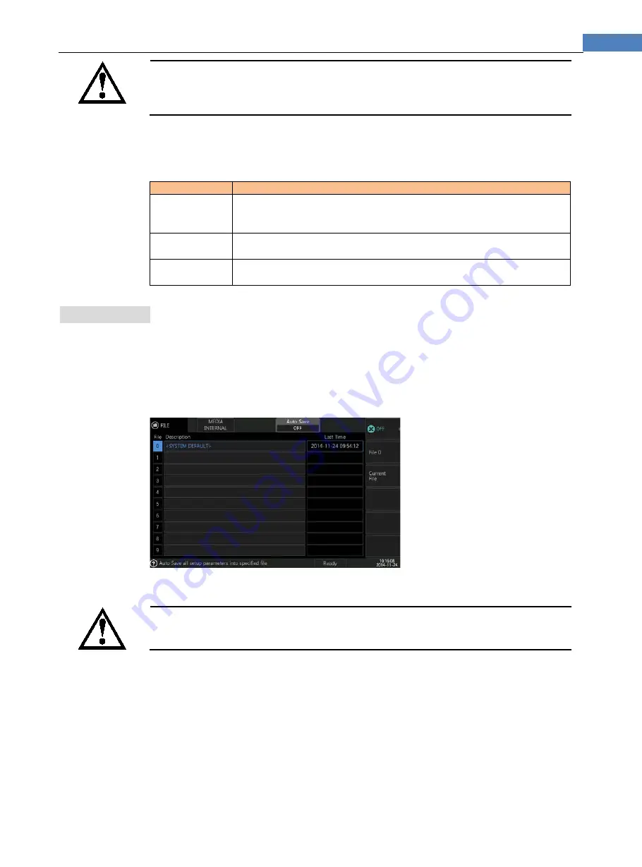
“[Auto Save] function” must be set by [Auto Save] option in [File] page, set [Auto Save] option
as [file 0] or [Current File]
Figure 4-1 Auto-Save Setting on File Page
If [Auto Save] is under state of [OFF], then users need to enter <FILE> page and manually save
set data into the file.
If the instrument is powered off due to accident power failure, the revised data will not automatically be saved.
For more details, please refer to chapter of <FILE> page.


