


Preliminary Technical Data
UG-1828
Rev. PrC | Page 331 of 338
External Path Delay Measurement (for DPD)
Connect the Tx1 output, through the chosen PA, to Rx1B input with a cable (an optional step attenuator can be added to the loop).
Configure the TES to indicate that the external path after PA exists in the
Board Configuration
tab. The DPD should be enabled from the
Advanced Features
tab. Run the script immediately after programming to make sure the device is in the “Calibrated” state. The state of the
part can be checked and changed from the View menu under Radio State.
This script runs the
ExternalPathDelay_Clibrate
cal to get the path delay. It then sets the path delay value and checks it to make sure it was
written correctly. The Delay will be displayed in the Output window in ps. This script can be run without the PA using just a cable or
cable and attenuator to test the script. For proper use case results the PA will be needed.
Setting the PLL Filter Bandwidth (for Phase Noise Optimization)
To test this script first begin by running a phase noise measurement using the default PLL settings. Stop transmitting on the Tx to load
and run the python script. Inside the script, you should only change PLL loop fitter bandwidth. Other PLL parameters should be kept the
same. (You can read them, change the bandwidth and then write it back). The change takes effect when the carrier is configured so you
need to read the carrier status and then configure it. This can only be performed when device is at calibrated state as shown in the script.
Start transmitting on the Tx and measure the phase noise again to observe the difference.
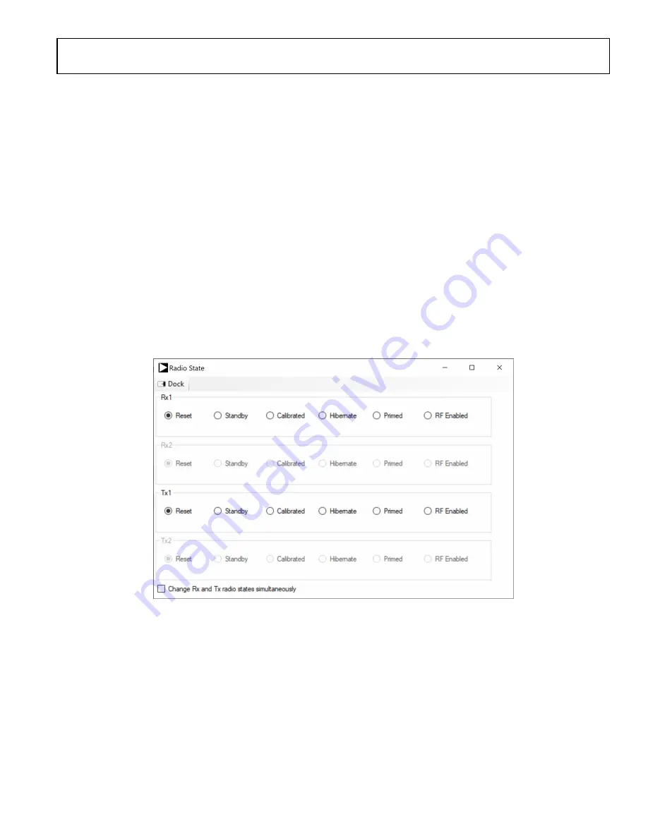
Radio State
Once board is connected, user can view/set radio state. This is under
View->Radio State
. Certain operations in the GUI can set radio to
certain states. User should be aware in what state the radio is operating on and control the GUI accordingly. User can also set the radio to
certain state from this window.
Figure 323. Radio State Window
Power/Temperature Monitoring
The ADRV9001 evaluation software allows user to monitor power usage of the system. On top there is a button
Power / Temp
Monitoring
, which shows detailed voltage, current and power status of each power domain. It also shows the temperature from an
internal temp sensor. Below is a screenshot of the power monitor window.
Note the VDDA_1P0 power domain is currently not supported by ADRV9001 and its readback should be ignored.


