Anaheim Automation DPC50501 Скачать руководство пользователя страница 11

September 2012

L010194

11

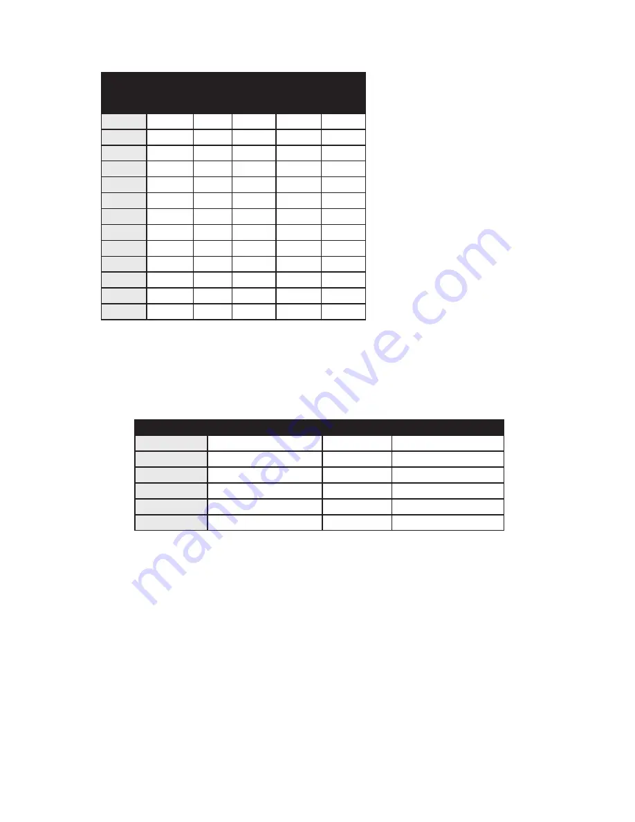
Step Motor Selection Guide

Anaheim Automation offers motor cable, making hookups quickly and easy!  Contact the 

factory of visit our website www.anaheimautomation.com for motor and cable offerings.

Part 

Number

Unipolar 

Rating

Series 

Peak 

Rating

Parallel 

Peak 

Rating

Series 

Current 

Setting

Parallel 

Current 

Setting

23Y206

3.0A

3.0A

6.0A

60%

100%

23Y210

5.0A

5.0A

10.0A

100%

100%

23Y306

3.0A

3.0A

6.0A

60%

100%

23Y310

5.0A

5.0A

10.0A

100%

100%

34Y108

4.0A

4.0A

8.0A

80%

100%

34Y207

3.5A

3.5A

7.0A

70%

100%

34Y307

3.5A

3.5A

7.0A

70%

100%

23Y108

4.0A

4.0A

8.0A

80%

100%

23Y106

3.0A

3.0A

6.0A

60%

100%

23Y104

2.0A

2.0A

4.0A

40%

80%

17Y302

---

1.0A

---

22%

---

17Y202

---

1.0A

---

22%

---

17Y102

---

1.0A

---

22%

---

Setting the Output Current

The output current on the DPC50501 is set by an onboard potentiometer.  This potentiometer deter-

mines the per phase peak output current of the driver.  The relationship between the output current 

and the potentiometer value is as follows:

Reducing Output Current

Reducing the output current is accomplished by setting switch 1 of the DIP switch to the ON position 

and occurs approximately 20mSec after the last positive going edge of the step clock input.  The 

amount of current per phase in the reduction mode is approximately 50% of the set current.  When 

the  current reduction circuit is activated, the current reduction resistor is paralleled with the current 

adjustment potentiometer.  This lowers the total resistance value, and thus lowers the per phase 

output current.

Determining Output Current

The output current for the motor used when microstepping is determined differently from that of a full/half 

step unipolar driver.  In the DPC50501, a sine/cosine output function is used in rotating the motor.  The 

output current for a given motor is determined by the motors current rating and the wiring configuration of 

the motor.  There is a current adjustment potentiometer used to set the output current of the DPC50501.  

This sets the peak output current of the sine/cosine waves.  The specified motor current (which is the 

unipolar value) is multiplied by a factor of 1.0, 1.4, or 2.0 depending on the motor configuration (series, 

half-coil, or parallel).

Peak Current Potentiometer Setting Peak Current Potentiometer Setting

0.5A

0%

3.0A

60%

0.6A

10%

3.5A

70%

0.9A

20%

4.0A

80%

1.5A

30%

4.5A

90%

2.0A

40%

5.0A

100%

2.5A

50%

--

July 2018

Содержание DPC50501

Страница 1: ...DPC50501 Programmable Driver Pack User s Guide 4985 E Landon Drive Anaheim CA 92807 e mail info anaheimautomation com 714 992 6990 fax 714 992 0471 website www anaheimautomation com A N A H E I M A U...

Страница 2: ...rrent 11 Determining Output Current 11 Step Motor Configurations 12 Connecting the Step Motor 13 Short Circuit Mis Wire and Over Current Conditions 13 Section 2 Controller Functions 14 Section 3 SMC50...

Страница 3: ...absolute positioning moves the controller automatically determines the proper direction to go and the number of steps to take The relative positioning will move a number of steps in the direction that...

Страница 4: ...r supply for PCL501 and PCL501PC 24V 1 2A 5V 3 5A Axis Selection Each controller will be addressed using 5 jumpers JP4 JP8 allowing the PC to address up to 32 controllers from one port The jumpers are...

Страница 5: ...grammable Logic Controller where the computer or PLC gives the controller serial commands to off load its processor For example A PLC can utilize its outputs to toggle the controller s inputs and gai...

Страница 6: ...TX RX to the first controller in the network Finally do the same on the terminal block of the controller to the converter box The diagram below illustrates how this configuration is connected RS422 sy...

Страница 7: ...generated in the error code register To read and clear the error with the software click on the Verify Parameters button located in the Motion Tab To read and clear the error while in Direct Mode use...

Страница 8: ...ference TB2 Pin Description 1 Phase A Phase 1 of the step motor 2 Phase Phase 3 of the step motor 3 Phase B Phase 2 of the step motor 4 Phase B Phase 4 of the step motor 5 MGND Motor Ground TB4 Pin De...

Страница 9: ...September 2012 L010194 9 Dimensions Wiring Diagram July 2018...

Страница 10: ...Motor Selection The DPC50501 s bipolar microstep driver is compatible with both bipolar and unipolar motor configurations i e 8 and 4 lead motors and 6 lead center tapped motors Step motors with low...

Страница 11: ...position and occurs approximately 20mSec after the last positive going edge of the step clock input The amount of current per phase in the reduction mode is approximately 50 of the set current When t...

Страница 12: ...nt rating by 1 4 to de termine the current setting potentiometer value This configuration will provide more torque at higher speeds when compared to the series configuration When configuring the motor...

Страница 13: ...are connected to pins 3 and 4 on connector TB4 The motors case can be grounded to pin 5 on connector TB4 Note The physical direction of the motor with respect to the direction input will depend on the...

Страница 14: ...oft limit switch Home to Home Limit This type homing differs in that only one limit switch is needed The home limit switch in this case causes the motor to ramp down to base speed reverse direction an...

Страница 15: ...on the input the pull up resistor source current is approximately 5mA This will make the inputs read like they are logi cally reverse A grounded input will read a 1 and an open input will read a 0 The...

Страница 16: ...lling the time it takes to go from maximum speed to base speed The higher the value the slower the motor will decelerate Range 1 to 255 Base Speed The base speed is the speed at which motion starts an...

Страница 17: ...2000 Windows XP Vista and Windows 7 Windows 95 98 NT ME 2000 XP Installation Option 1 1 Insert the CD into the drive 2 From the Program Manager select Start Run 3 Enter D setup and click OK use the a...

Страница 18: ...gs Axis Select axis 0 31 for multi drop units Autostart Program Enable Disable program execution on power up New Program Start editing a new program Open Program Open an existing program from disk Sav...

Страница 19: ...l seek the home position by moving towards home switch One switch is required to stop anti backlash Home using Soft and Home Switches Motor will seek the home position by moving towards home switch bu...

Страница 20: ...rev motor running in half step mode Send Program to Controller Send current program to the controller View Program in Controller View program in the controller memory Enable Autostart Program will st...

Страница 21: ...ow The controller has a maximum available memory of 2047 bytes each instruction can use from 1 to 5 bytes Currently Selected Line The currently selected line is indicated in the program by the right p...

Страница 22: ...orks similar to the Motion Tab Sheet explained above in the Getting Started section To add a line of motion control select appropriate motion control from the list then enter the required value for th...

Страница 23: ...itiate motion in the direction last entered seeking the soft input first to slow the motor down to base speed then to stop when the home limit is triggered Home to Home Limit Command will initiate mot...

Страница 24: ...ked input box If the inputs 1 through 4 do not match the next line is skipped Set Outputs The outputs can be turned on 1 or off 0 These outputs can be used to trigger PLC operations relays solenoids e...

Страница 25: ...lution per second RPS PPS Convert from revolution per second to pulses per second Steps Per Rev Enter the number of steps per revolution of the step motor The default is for a 200 step rev motor in ha...

Страница 26: ...ge Return After the command the controller will return a SMC50 the current revision number Note In direct talk mode each command is followed by a carriage return The unit communicates in half duplex m...

Страница 27: ...n profile which can be an integer value between 1 and 255 The lower the value the faster the motor acceleration so a 1 is the fastest profile and 255 is the slowest Range 1 255 B Base Speed Format B v...

Страница 28: ...er of clocks out of the controller An N or P command must be entered before the G command P Absolute Position Format P value Description This command calculates and sets the number of steps necessary...

Страница 29: ...pe 0 homing the controller will send clocks until a soft limit is reached then ramp down to base speed Clocks will continue until a home or hard limit is reached H1 In type 1 homing the unit will move...

Страница 30: ...hey are pulled low For example if all inputs are active grounded the command will return a 15 If all inputs are inactive open the command will return a 0 Input 1 is the LSB input 2 is the second bit i...

Страница 31: ...the same 8 Click on Connect icon to communicate with the controller 9 If problems still exist contact Anaheim Automation Tech Support Problem There is no power to the controller Possible Solutions 1...

Страница 32: ...ller Please check to see that the command being sent is valid 16 Motor Error Motor speed profiles are set incorrectly Please make sure that the base speed is less than the max speed and that the speed...

Страница 33: ...ction 6 Sample Programs Sample Program 1 Sample Program 1 illustrates a typical application where a system moves to a specific position required The sample program shows how to use motion and go to in...

Страница 34: ...ple Program 2 illustrates a typical application where a system is first sent home to a datum or 0 position This sample program shows how a motor will move to a 3 different positions utilizing some of...

Страница 35: ...September 2012 L010194 35 July 2018...

Страница 36: ...le for Direct Mode ASCII Symbol Hex Value ASCII Symbol Hex Value Carriage Return 0D I 49 0 30 J 4A 1 31 L0 4C 30 2 32 LS 4C 53 3 33 M 4D 4 34 N 4E 5 35 O 4F 6 36 P 50 7 37 S 53 8 38 V 56 9 39 Z 5A A 4...

Страница 37: ...Anaheim Automation products in life support applications assumes all risks of such use and indemnifies Anaheim Automation against all damages LIMITED WARRANTY AllAnaheimAutomation products are warrant...

Отзывы: