


11
Temposonics
®
GB-Series SSI
Operation Manual
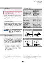
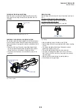
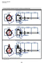
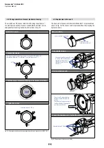
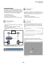
Installation of GB with threaded flange »M« & »T«
Fix the sensor rod via threaded flange M18×1.5-6g or ¾"-16 UNF-3A.
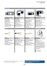
Base unit (Example: M16 connector)
34.5
(1.36)
Ø 6.81 (Ø 0.27)
Controlling design dimensions are in millimeters and measurements in ( ) are in inches
Unless otherwise stated, apply to the general tolerances according to DIN ISO 2768-m
Fig. 8: Temposonics
®
GB-B
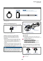
Fig. 9:
Mounting example of threaded flange »M« & »T«
NOTICE
The GB-B is only for replacement.
Use the GB-B sensor with a rod of the GB-M or GB-T sensor only.
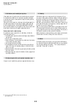
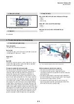
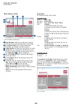
Installation of a rod-style sensor in a
hydraulic
cylinder
The rod-style version has been developed for direct stroke
measurement in a
hydraulic
cylinder. Mount the sensor via
threaded flange.
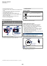
• Mounted on the face of the piston, the position magnet travels
over the rod without touching it and indicates the exact position
through the rod wall – independent of the hydraulic fluid.
• The pressure resistant sensor rod is installed into a bore in the
piston rod.
• The base unit is mounted by means of only three screws. It is the
only part that needs to be replaced if servicing is required, i.e. the
hydraulic circuit remains closed. For more information see chapter
“4.6 Replacement of base unit” on page 14.
Fig. 10:
Sensor in cylinder
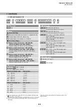
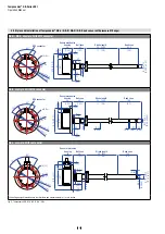
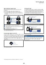
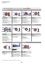
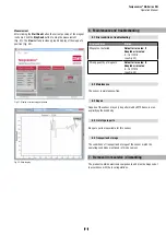
Hydraulics sealing
There are two ways for sealing the flange contact surface (Fig. 11):
1.
A sealing by using an O-ring (e.g. 22.4 × 2.65 mm (0.88 × 0.1 in.))
in a cylinder end cap groove.
2. A sealing via an O-ring in the undercut.
For threaded flange (¾"-16 UNF-3A) (GB-T):
O-ring 16.4 × 2.2 mm (0.65 × 0.09 in.) (part no. 560 315)
For threaded flange (M18×1.5-6g) (GB-T):
O-ring 15.3 × 2.2 mm (0.60 × 0.09 in.) (part no. 401 133)
In the case of threaded flange M18×1.5-6g, a screw hole based on
ISO 6149-1 (Fig. 12) must be provided. See ISO 6149-1 for further
information.
Fig. 11:
Possibilities of sealing
NOTICE
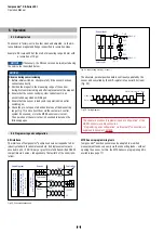
The orientation of the sensor electronics housing respectively of
the electrical connection of sensor models GB-M and GB-T can be
MTS recommendation
R
R
R
Fastening torque
50 Nm
In the event of servicing, the sensor rod
with flange remains in the cylinder
Position magnet
Base unit
The sensor electronics housing
with sensing element can be replaced
Sealing via O-ring
in the flange undercut
Sealing via O-ring
in cylinder end cap groove