

12
Temposonics
®
GB-Series SSI
Operation Manual
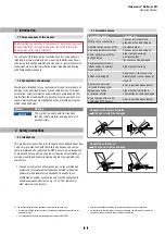
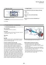
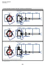
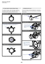
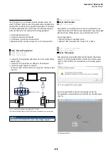
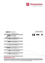
Fig. 12:
Notice for threaded flange M18×1.5-6g based on DIN ISO 6149-1
•
Note the fastening torque of 50 Nm.
•
Seat the flange contact surface completely on the cylinder mounting
surface.
• The cylinder manufacturer determines the pressure-resistant
gasket (copper gasket, O-ring, etc.).
• The position magnet should not grind on the sensor rod.
•
The piston rod drilling (≥ Ø 13 mm (≥ Ø 0.52 in.)) depends on the
pressure and piston speed.
• Adhere to the information relating to operating pressure.
• Protect the sensor rod against wear.
Notice for metric threaded flange
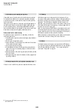
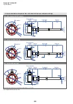
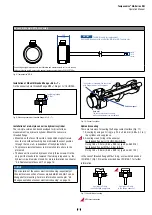
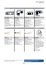
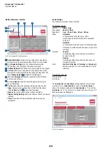
4.4 Magnet installation
Typical use of magnets
Magnet
Benefits
Ring magnets
•
Rotationally symmetrical magnetic field
U-magnets
• Height tolerances can be compensated
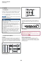
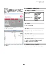
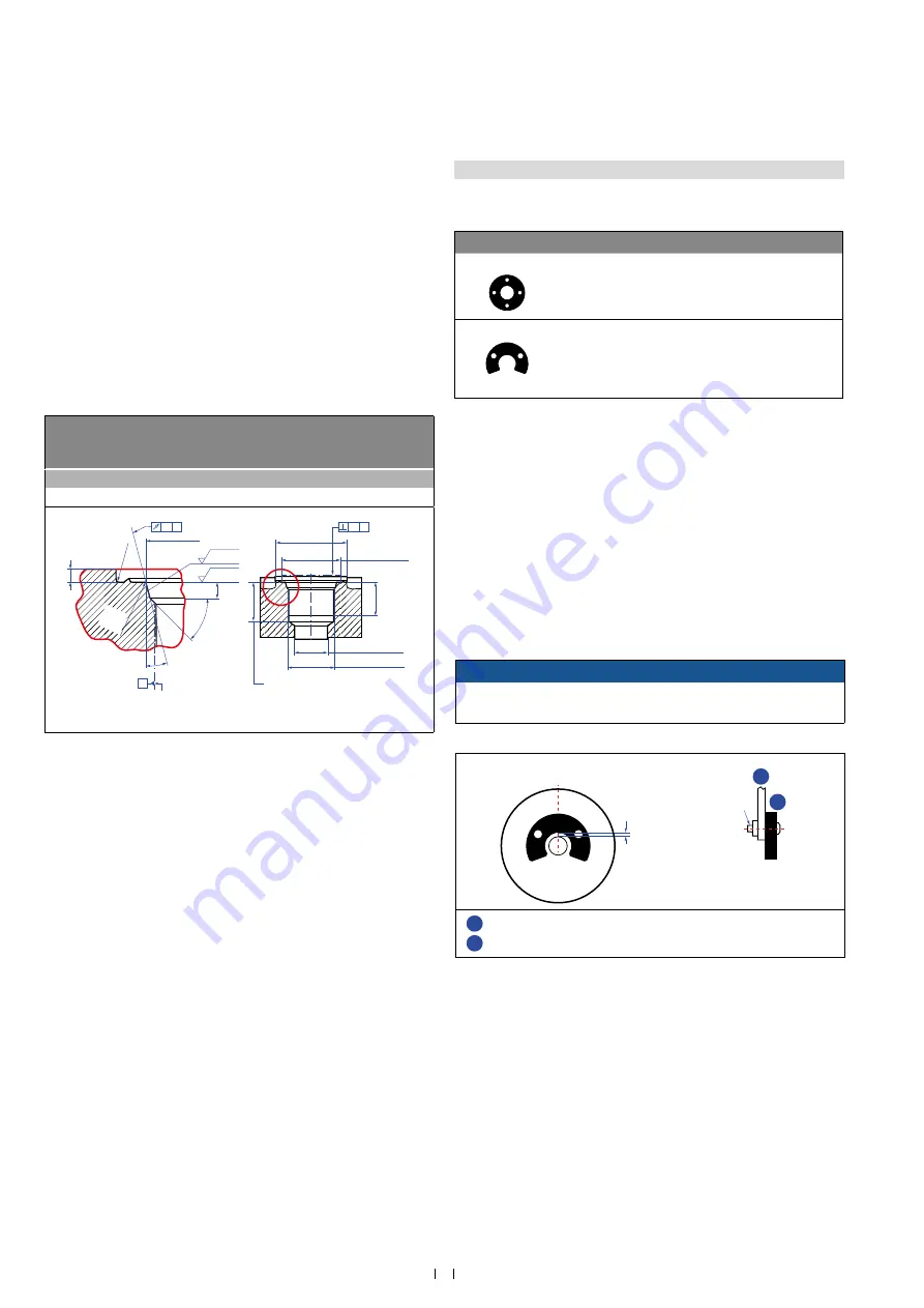
Mounting ring magnets and U-magnets
Install the magnet using non-magnetic material for mounting
device, screws, spacers etc.. The magnet must not grind on
the sensor rod. Alignment errors are compensated via the air gap.
•
Permissible surface pressure: Max. 40 N/mm
2
•
Fastening torque for M4 screws: 1 Nm; use washer, if necessary
• Minimum distance between position magnet and any magnetic
material has to be 15 mm (0.6 in.) (Fig. 15).
• If no other option exists and magnetic material is used, observe the
specified dimensions (Fig. 15).
Fig. 13:
Typical use of ring magnets and U-magnets
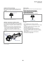
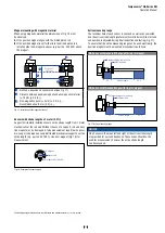
NOTICE
Mount ring magnets and U-magnets concentrically.
Do not exceed the maximum acceptable gap.
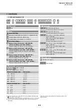
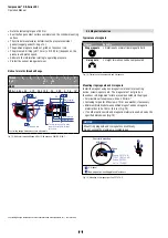
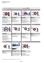
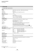
Fig. 14:
Mounting of U-magnet, part no. 251 416-2
Controlling design dimensions are in millimeters and measurements in ( ) are in inches
Thread
(d
1
×P)
d
2
d
3
d
4
d
5
+0.1
0
L
1
+0.4
0
L
2
L
3
L
4
Z°
±1°
GB-M
M18×1.5-6g ≥ 65
≥ 13
24.5
19.8
2.4
28.5
2 26
15°
Ød
5
Ra 3.2
Ra 3.2
Pitch diameter
A
A
Thread
(d
1
× P)
Ød
3
(Reference)
A
Ød
2
Ød
4
(Gauging)
This dimension applies when
tap drill cannot pass through
entire boss.
≤ R0.4
R0.3 R0.1
Z°
45
° ±
5°
L
3
L
1
L
2
L
4
A
0.1
A
0.2
Controlling design dimensions are in millimeters
M4
1
2
Air gap
Concentric mounting
of U-magnet
Part no. 201 553:
3 ±1 (0.12 ±0.04)
Part no. 251 416-2:
1.75 ±1 (0.07 ±0.04)
U-magnet
Non-magnetic mounting plate and fasteners
1
2