


15
Temposonics
®
GB-Series SSI
Operation Manual
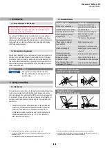
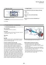
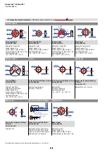
4.7 Electrical connection
Placement of installation and cabling have decisive influence on the
sensor‘s electromagnetic compatibility (EMC). Hence correct
installation of this active electronic system and the EMC of the entire
system must be ensured by using suitable metal connectors, shielded
cables and grounding. Overvoltages or faulty connections can damage
the sensor electronics despite protection against wrong polarity.
Instruction for connection
• Use low-resistance twisted pair and shielded cables. Connect the
shield to ground externally via the controller equipment.
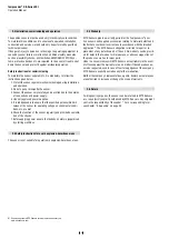
• Keep control and signal leads separate from power cables and
sufficiently far away from motor cables, frequency inverters, valve
lines, relays, etc..
• Use only metal connectors and connect the shielding to the
connector housing.
• Keep the connection surface at both shielding ends as large as
possible. Connect the cable clamps to function as a ground.
• Keep all non-shielded leads as short as possible.
• Keep the ground connections short and with a large cross section.
Avoid ground loops.
• With potential differences between machine and electronics earth
connections, no compensating currents are allowed to flow across
the cable shielding.
Recommendation: Install potential compensating leads with large
cross section, or use cables with separate double shielding, and
connect only one end of the shield.
•
Use only stabilized power supplies and make sure that the specified
connecting values are met.
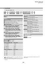
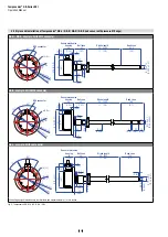
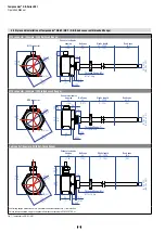
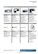
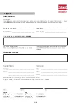
Fig. 20:
Connector wiring D84 (M12)
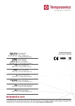
Fig. 21:
Connector wiring D70 (M16)
Connector wiring
Connect the sensor directly to the control system, indicator or other
evaluating systems as follows:
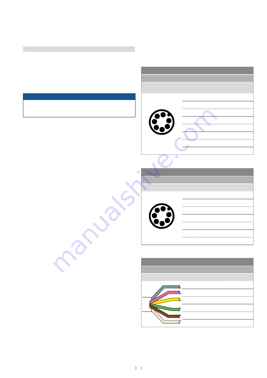
Fig. 22:
Connector wiring cable outlet
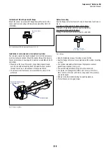
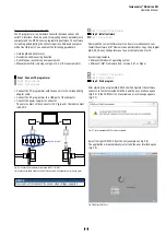
NOTICE
• Do not mount the sensors in the area of strong magnetic or
electric noise fields.
•
Never connect / disconnect the sensor when voltage is applied.
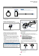
Grounding of rod sensors
Connect the sensor electronics housing to the machine ground via
pressure fit flange respectively via threaded flange.
D84
power supply
M12 male connector
(A-coded)
Pin
Function
1
4
2
6
3
5
7
View on sensor
1
Clock (+)
2
Clock (−)
3
Data (+)
4
Data (−)
5
Not connected
6
Not connected
7
+24 VDC (−15 / +20 %)
8
DC Ground (0 V)
D70
power supply
M16 male connector
Pin
Funktion
1
4
2
6
3
5
7
View on sensor
1
Data (−)
2
Data (+)
3
Clock (+)
4
Clock (−)
5
+24 VDC (−15 / +20 %)
6
DC Ground (0 V)
7
Not connected
GB with cable outlet (H
XX
/ T
XX
/ V
XX
)
power supply
Cable
Color Function
GY
Data (−)
PK
Data (+)
YE
Clock (+)
GN
Clock (−)
BN
+24 VDC (−15 / +20 %)
WH
DC Ground (0 V)