


7
Temposonics
®
GB-Series SSI
Operation Manual
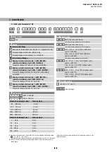
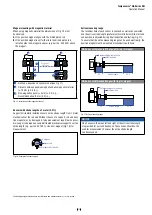
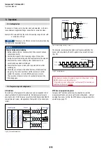
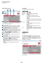
3.2 Nameplate (example)
3.3 Approvals
CE certification
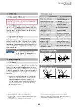
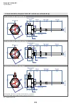
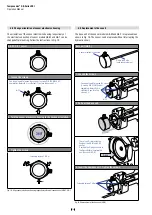
4. Product description and commissioning
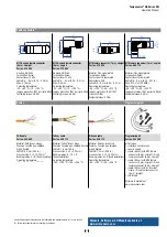
3.4 Scope of delivery
GB-J / GB-K / GB-N / GB-S
(rod sensor with pressure fit flange)
:
• Sensor
• O-ring
• Back-up ring
GB-M / GB-T
(rod sensor with threaded flange)
:
• Sensor
• O-ring
GB-B
(base unit for rod sensor with threaded flange)
:
• Sensor
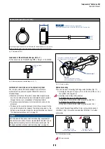
4.1 Functionality and system design
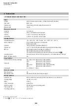
Product designation
• Position sensor Temposonics
®
GB-Series
Sensor model
• Temposonics
®
GB-J, GB-K, GB-N, GB-S, GB-M, GB-T (sensor rod)
• Stroke length 25
…
3250 mm (1…128 in.)
Output signal
• SSI
Application
Temposonics
®
position sensors are used for measurement and con-
version of the length (position) variable in the fields of automated
sys tems and mechanical engineering.
Principle of operation and system construction
The absolute, linear position sensors provided by MTS Sensors
rely on the company’s proprietary Temposonics
®
magnetostrictive
technology, which can determine position with a high level of
precision and robustness. Each Temposonics
®
position sensor
consists of a ferromagnetic waveguide, a position magnet, a strain
pulse converter and supporting electronics. The magnet, connected
to the object in motion in the application, generates a magnetic field
at its location on the waveguide. A short current pulse is applied to
the waveguide. This creates a momentary radial magnetic field and
torsional strain on the waveguide. The momentary interaction of the
magnetic fields releases a torsional strain pulse that propagates the
length of the waveguide. When the ultrasonic wave reaches the end of
the waveguide it is converted into an electrical signal. Since the speed
of the ultrasonic wave in the waveguide is precisely known, the time
required to receive the return signal can be converted into a linear
position measurement with both high accuracy and repeatability.
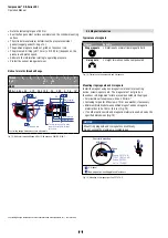
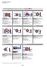
Modular mechanical and electronic construction
• The sensor rod protects the inner sensor element.
• The sensor electronics housing, a rugged stainless steel
construction, contains the complete electronic interface with active
signal conditioning.
• The external position magnet is a permanent magnet. Mounted on
the mobile machine part, it travels along the sensor rod and triggers
the measurement through the sensor rod wall.
• The sensor can be directly connected to a control system. Its
electronics generates a position signal output proportional to the
start and end of the active measuring range.
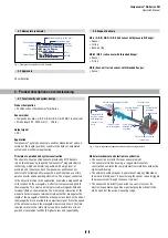
Fig. 1: Example of a nameplate of a GB-S sensor
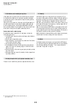
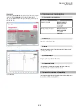
Fig. 2:
Time-of-flight based magnetostrictive position sensing principle
5
Sensing element
(Waveguide)
Position magnet (Magnetic fi eld)
Torsional strain
pulse converter
4
Current pulse
generates
magnetic fi eld
Interaction with
position magnet
fi eld generates
torsional strain
pulse
Torsional strain
pulse propagates
Strain pulse
detected by
converter
Time-of-fl ight converted
into position
1
2
3
GBS0850MD701S2G5100SC
0.02 mm / 24 Bit gray
Grd.: 2807.46 m/s
FNr. 1601 0376
1601037616010376160103761601
Sensor model
Stroke length (e.g. 850 mm)
Connection type
Output
version
Part no.
Output
Production no.
Week
Year