


18
Temposonics
®
GB-Series SSI
Operation Manual
5. Operation
5.1 Getting started
The sensor is factory-set to its order sizes and adjusted, i.e. the dis
-
tance between magnet and flange is specified in resolution steps.
Example: SSI value 4000 at the start of measuring range 40 mm with
a resolution of 10 µm
NOTICE
If necessary, the SSI sensors can be re-adjusted using
the service tool described below.
5.2
Programming and configuration
SSI interface
The interface of Temposonics
®
position sensors corresponds to SSI
industry standard for absolute encoders. Its displacement value is
encoded in a 24 / 25 bit binary or gray format and transmitted RS422
compatible via 4 wires – independent of data width of the code (reso
-
lution).
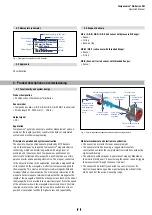
The absolute, parallel position data is continually updated by the
sensor and converted by the shift-register into a serial bit stream
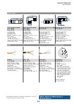
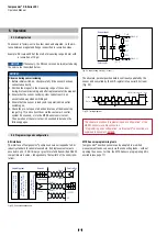
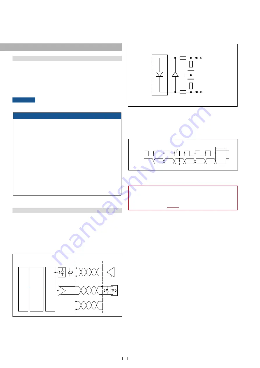
Fig. 23:
Schematic connection
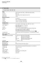
Fig. 24:
Input wiring clock (+) / clock (
−)
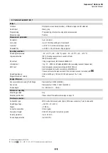
Fig. 25:
Timing diagram
MTS Sensors programming tools
Temposonics
®
position sensors can be adapted to modified
measurement tasks very easily via the connecting leads – without
opening the sensor. For this, the MTS Sensors programming kit is
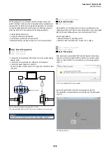
This chapter describes “programming and configuration” of the
GB SSI sensor via cable connection.
“Programming and configuration” via Bluetooth
®
connection are
NOTICE1
Observe during commissioning
1. Before initial switch-on, check carefully if the sensor has been
connected correctly.
2. Position the magnet in the measuring range of the sensor
during first commissioning and after replacement of the magnet.
3. Ensure that the sensor control system cannot react in an
uncontrolled way when switching on.
4. Ensure that the sensor is ready and in operation mode after
switching on
.
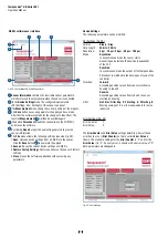
5. Check the pre-set span start and end values of the measuring
range (Fig. 17) and correct them via the customer’s control
system if necessary, or via the MTS Sensors service tool.
The operation of the service tool is described in detail on the
following pages.
Sensor input
91 Ω
7 mA
Clock (+)
100 Ω
LED
100 Ω
Clock (−)
91 Ω
Optocoupler
2 V
1 nF
1 nF
Clock (+)
Data (+)
MSB
LSB
Clock interval min. 16 µs
Logic diagram
Sensor
Controller
Clock (+)
Clock (−)
Optocoupler
Driver
Data (+)
Data (−)
+24 VDC
0 V
ASIC for parallel and absolute position data
Microprocessor system position value = 24 / 25 bit
binar
y or gray
Shift register
parallel serial converter