
13
Temposonics
®
GB-Series SSI
Operation Manual
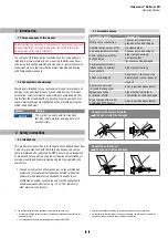
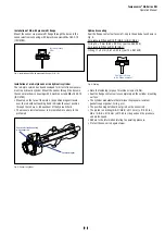
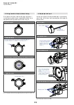
Magnet mounting with magnetic material
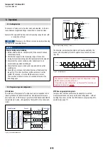
When using magnetic material the dimensions of Fig. 15 must
be observed.
A.
If the position magnet aligns with the drilled piston rod
B.
If the position magnet is set further into the drilled piston rod,
install another non-magnetic spacer (e.g. part no. 400 633) above
the magnet.
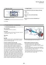
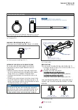
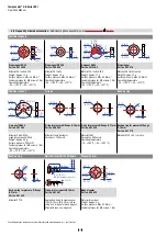
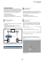
Sensors with stroke lengths ≥ 1 meter (3.3 ft.)
Support horizontally installed sensors with a stroke length from 1 meter
mechanically at the rod end. Without the use of a support, rod and posi-
tion magnet may be damaged. A false measurement result is also possi-
ble. Longer rods require evenly distributed mechanical support over the
entire length (e.g. part no. 561 481). Use an U-magnet (Fig. 16) for
measurement.
Fig. 16:
Example of sensor support
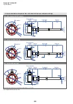
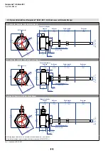
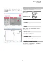
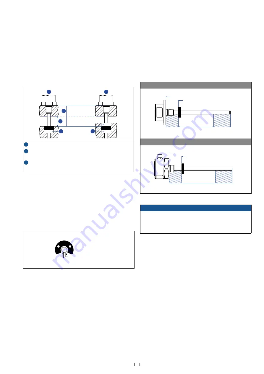
Active measuring range
The technical data of each sensor is checked as well as documented
and the active stroke length (useful electrical stroke) with its start and
end position is adjusted during final inspection and testing (Fig. 17).
To ensure that the entire measuring range can be used electrically, the
position magnet must be mounted mechanically as follows:
GB-Series with pressure fit flange with ring / U-magnet
40
Stroke length
63.5
Reference edge of mounting
Start position
GB-Series with threaded flange with ring / U-magnet
40
Stroke length
63.5
Reference edge of mounting
Start position
Fig. 17: Active measuring range
NOTICE
On all sensors, the areas left and right of the active stroke length
are provided for null and dead zone. These zones should not be
used for measurement, however the active stroke length
can be exceeded.
Controlling design dimensions are in millimeters and measurements in ( ) are in inches
Fig. 15:
Installation with magnetic material
Magnet
Magnet
1
2
3
3
A
B
Magnetic
material
1
Null zone, depends on sensor model (see Fig. 17)
2
Distance between position magnet and any magnetic material
(≥ 15 mm (≥ 0.6 in.))
3
Non-magnetic spacer (≥ 5 mm (≥ 0.2 in.)) –
Recommendation: 8 mm (0.31 in.)
U-magnet
Sensor rod
Non-magnetic fixing clip