

5
Temposonics
®
GB-Series SSI
Operation Manual
3.
Identification
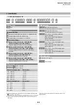
3.1 Order code Temposonics
®
GB
Trademarks and trade names mentioned in this document are those of their
respective owners.
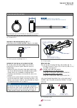
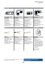
d Connector type
D 8 4
M12 male connector (8 pin)
(Note the operating temperature of the connector)
D 7 0
M16 male connector (7 pin)
(Note the operating temperature of the connector)
H X X
H01…H10 (1…10 m)
4
XX m PUR cable
(part no. 530 052)
H03…H33 (3…33 ft)
4
XX ft
PUR cable
(part no. 530 052)
(Note the operating temperature of the cable)
T X X
T01…T10 (1…10 m)
4
XX m Teflon
®
cable
(part no. 530 112)
T03…T33 (3…33 ft)
4
XX ft
Teflon
®
cable
(part no. 530 112)
V X X
V01…V10 (1…10 m)
4
XX m Silicone cable
(part no. 530 113)
V03…V33 (3…33 ft)
4
XX ft
Silicone cable
(part no. 530 113)
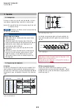
e Operating voltage
1
+24 VDC (−15 / +20 %)
a Sensor model
G B
Rod
3/
The sensor in stainless steel 1.4404 (AISI 316L) is only available with following option:
S
(−40…+90 °C / −40…+194 °F)
*/
Non standard stroke lengths are available; must be encoded in 5 mm / 0.1 in. increments
4/
Encode in meters if using metric stroke length. Encode in feet if using US customary
stroke length
1
2
3
4
5
6
7
8
9
10
11
12
13
14
15
16
17
18
19
20
21
G B
1
S
C
a
b
c
d
e
f
g
h
.
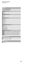
c Stroke length
X X X X M
0025…3250 mm
X X X X U
001.0…128.0 in.
Standard stroke length (mm)*
Ordering steps
25… 500 mm
5 mm
500… 750 mm
10 mm
750…1000 mm
25 mm
1000…2500 mm
50 mm
2500…3250 mm
100 mm
Standard stroke length (in.)*
Ordering steps
1… 20 in.
0.2 in.
20… 30 in.
0.5 in.
30… 40 in.
1.0 in.
40…100 in.
2.0 in.
100…128 in.
4.0 in.
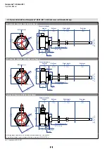
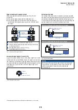
b Design
GB with threaded flange
B
Base unit for threaded flanges »M« and »T« (replacement only)
M
Threaded flange with flat-face, M18×1.5-6g
T
Threaded flange with raised-face, ¾"-16 UNF-3A
GB with pressure fit flange
J Housing material stainless steel 1.4305 (AISI 303),
rod material stainless steel 1.4301 (AISI 304)
Pressure fit flange Ø 21 mm, Ø 12.7 mm rod, 800 bar
K Housing material stainless steel 1.4305 (AISI 303),
rod material stainless steel 1.4306; 1.4307 (AISI 304L)
Pressure fit flange Ø 18 mm, Ø 10 mm rod with bushing
on rod end
N Housing material stainless steel 1.4404 (AISI 316L),
rod material stainless steel 1.4404 (AISI 316L)
3
Pressure fit flange Ø 18 mm, Ø 10 mm rod
S Housing material stainless steel 1.4305 (AISI 303),
rod material stainless steel 1.4306; 1.4307 (AISI 304L)
Pressure fit flange Ø 18 mm, Ø 10 mm rod
f
See next page
g h