Ampetronic D Series Installation Handbook & User Guide
Page 11
MAIN Menu
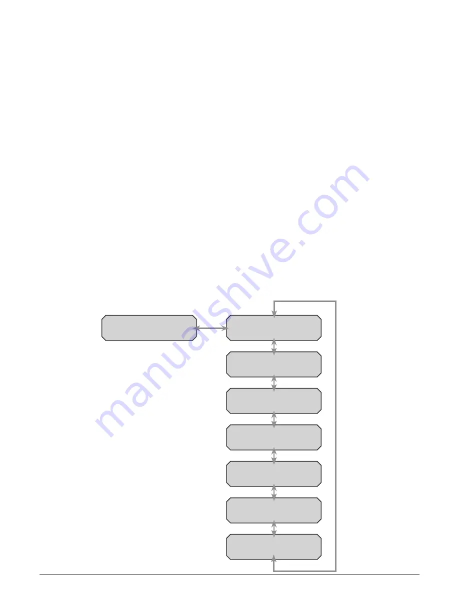
This is a comprehensive menu that allows access to most settings of the driver - see menu flow
chart. At the top of the main menu the driver will display “AMPETRONIC D1X-X” and the name
of the driver which defaults to "Name Not Set " . From this screen pressing the ENTER button will
move to the top level menu and display “Main Menu” “1 Input” .
Pressing the LEFT will decrement the menu number (decrementing from “1 Input” will move to “7
Ethernet”) and RIGHT buttons will increment the menu number (incrementing from “7 Ethernet” will
move to “1 Input”). Once the required menu is shown, pressing “ENTER” will move into that menu.
Pressing LEFT and RIGHT will move around the options within this menu as above . Pressing
BACK returns to the top level menu whilst pressing ENTER selects a parameter to be edited . At
this point the LED on the ENTER key goes out as this key no longer has a function and the LED on
the INCREMENT and DECREMENT buttons turns on to show that a value can be altered .
Editing Values:
If the value being edited is a numerical value then the cursor will flash over the
digit that will be altered by pressing the INCREMENT or DECREMENT button . To change the
cursor position press the LEFT or RIGHT buttons . The edited position wraps around from the least
significant digit to the most significant and vice versa. If the edited digit is incremented past 9 or
decremented below 0, a carry or borrow of the next most significant digit will occur. If the edited
value is a list (for example test signal sources), then the INCREMENT and DECREMENT buttons
will navigate up and down this list wrapping from top to bottom and bottom to top . Note that the
driver settings are updated every time the INCREMENT or DECREMENT buttons are pressed . In
the case of the MLC settings this can mean that the driver seems to pause momentarily between
button presses as there is a time required for calculation of the new filter coefficients.
Note:
Only Current, Config, Diagnostics and Ethernet menus are available in Slave mode.
Tier 1 Menu Structure
Home Screen
1 . Input
2 . Current
3 . Test Signals
4 . MLC Setup
5. Config
6 . Diagnostics
7 . Ethernet
Содержание d series
Страница 1: ...D Series Installation Handbook User Guide www ampetronic co...
Страница 2: ......
Страница 45: ...INSTALLATION NOTES Ampetronic D Series Installation Handbook User Guide Page 43...
Страница 46: ...INSTALLATION NOTES Ampetronic D Series Installation Handbook User Guide Page 44...
Страница 47: ...INSTALLATION NOTES Ampetronic D Series Installation Handbook User Guide Page 45...
Страница 48: ...Contents Copyright Ampetronic Ltd 2016 All rights reserved UP1 9001 4...


