Installation Guide
5 - 3
Thermal Imaging System
NIR-B Borescope
Electrical Auto Retract
8)
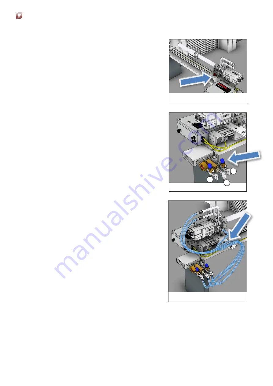
Assemble the camera jacket by undoing the red
handle and opening the clamp, seating the body
of the jacket and tightening the clamp.
Attach the port seal by sliding it over the end of
the tube and securing in position using the 4 x
M6 bolts. This can be adjusted later as required.
Fig. 5-8
Fig. 5-9
1
2
3
9)
Assemble the water and air sensor assemblies
via the three connection points.
Attach all three sections in the order shown
using the ½ in BSPP swivel adaptors, two
suitable spanners and PTFE tape.
Make sure that the male ends of the sensor
assemblies are pointing downward (these will
be adjusted later if required).
Fig. 5-10
10) Attach the water and air supply hoses from the
sensors to the system.
Mark a point on each hose section, approx.
820 mm / 32 in from one end. Secure this point
on each hose as shown using the bracket
provided with the measured 820 mm / 32 in
section of each hose to the left (as per view
shown).
Secure the left-hand side of each hose to the
water-jacket and the right-hand side to the
1/2 in BSPP male fittings on the water sensor
assemblies as per installation drawing sheets 5
& 6.
3 Nm


