American-Lincoln
FORM NO. 56041704 - 35
6150
BATTERY SERVICE INSTRUCTIONS
BATTERY CHARGING INSTRUCTIONS - cont.
Check the liquid level in the battery at least once a week and add water when low. Use only distilled water.
Fill the batteries after charging the batteries to prevent electrolyte from spilling over on the tops of the
batteries during the charging process.
WARNING
The use of an extension cord with the charger should be avoided. Risk of fi re and electrical shock
is possible if the wrong type or size extension cord is used. If an extension cord must be used, only
use a three conductor number 12 AWG cord with ground, properly wired, in good electrical condition
and keep it as short as possible. Locate all cords so that they cannot be stepped on, tripped over, or
otherwise subjected to damage or stress.
WARNING
Verify that the AC power source to which the charger is to be connected is capable of supplying the
current specifi ed on the charger nameplate.
WARNING
Keep all charger ventilation holes at least 2 inches away from walls or other objects. Do not allow
vent holes to become obstructed.
WARNING
Do not operate charger that has been damaged or shows physical signs of damage. Have charger
serviced by a qualifi ed professional repair person.
WARNING
Disconnecting the battery connector with the key switch in the “I” position will cause sparks that
could ignite explosive hydrogen gas generated by the batteries. To prevent serious injury or possible
property damage, Turn key switch to “O” position before disconnecting battery cable from machine
for charging or service.
WARNING
Lead acid batteries generate gases which can cause an explosion. Keep sparks and fl ames away
from batteries. NO SMOKING. Charge batteries only in area with good ventilation and always leave
the seat compartment cover open while charging batteries. Do not disconnect the charger from the
batteries before disconnecting the AC power cord. Disconnecting the battery cable with the charger
plugged in could cause an explosion.
TO CHARGE THE MOTOR POWER BATTERIES (Battery Powered Machines Only)
1. Read the detailed instructions provided on the charger.
2. Be sure all controls are “OFF” and machine is located in an area with good ventilation.
3. Open the seat compartment cover. The cover must remain open during the charging process. Use the
seat compartment latch to hold the cover open.
4. Disconnect the battery from machine power supply cable using the quick disconnect provided.
5. Connect the charger cable to the battery connector.
6. Plug the charger into properly grounded AC outlet. Be sure to verify the operating voltage of your
charger.
The chargers supplied with machine operate at 115 VAC @ 60 HZ or 230 VAC @ 50 HZ.
7. The charger will begin charging the batteries after a short period of time. The charger will shut off
automatically when the charging process is complete.
8. Unplug the charger from the grounded AC outlet before disconnecting the charger from the battery.
9. Disconnect the charger cable from the battery.
10. Check the electrolyte level in the battery after charging. Add distilled water if needed.
11. Reconnect the machine power supply cable to the battery cable.
12. Lower the seat compartment cover and perform the pre-start checks before operating the machine.
SERVICE INSTRUCTIONS
Содержание 6150
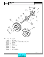
Страница 39: ...FORM NO 56042480 6150 IC 4 06 5 REAR WHEEL 07 10 ...
Страница 41: ...FORM NO 56042480 6150 IC 6 06 5 VAC FAN 07 10 ...
Страница 45: ...FORM NO 56042480 6150 IC 10 06 5 FLAP ASSEMBLY WHEEL WELL 07 3 C 1227 ...
Страница 51: ...FORM NO 56042480 6150 IC 16 06 5 C1250 H46 H43 H39 H47 H53 SIDE BROOM ASSEMBLY 07 3 ...
Страница 53: ...FORM NO 56042480 6150 IC 18 06 5 SIDE BROOM LIFT SYSTEM 07 10 ...
Страница 55: ...FORM NO 56042480 6150 IC 20 06 5 SIDE BROOM LEVER 07 3 H50 H54 H35 H46 H54 H85 H113 H52 C 1218 ...
Страница 57: ...FORM NO 56042480 6150 IC 22 06 5 BROOM CHAMBER FLAPS SEALS 07 10 ...
Страница 59: ...FORM NO 56042480 6150 IC 24 06 5 BRAKE PEDAL 80805 1 6 05 07 3 ...
Страница 63: ...FORM NO 56042480 6150 IC 28 06 5 SEAT FLOOR ASSEMBLY 07 10 ...
Страница 71: ...FORM NO 56042480 6150 IC 36 06 5 CONTROL RELIEF VALVE 3 CYL KUBOTA GAS DIESEL 07 3 ...
Страница 73: ...FORM NO 56042480 6150 IC 38 06 5 FWD REV CONTROL 2 CYL KAWASAKI GAS 07 10 ...
Страница 75: ...FORM NO 56042480 6150 IC 40 06 5 FW REV CONTROL 3 CYL KUBOTA GAS DIESEL 07 3 ...
Страница 79: ...FORM NO 56042480 6150 IC 44 06 5 C1222A2 TORQUE HOSE CLAMPS 21 25 FT LBS RESERVOIR 3 CYL KUBOTA GAS DIESEL ...
Страница 81: ...FORM NO 56042480 6150 IC 46 06 5 FUEL TANK GAS 07 10 ...
Страница 83: ...FORM NO 56042480 6150 IC 48 06 5 FUEL TANK DIESEL 07 10 ...
Страница 87: ...FORM NO 56042480 6150 IC 52 06 5 80806 2 2 05 HOPPER COVERS GASKET ASSEMBLY ...
Страница 91: ...FORM NO 56042480 6150 IC 56 06 5 H26 H80 H86 H26 H98 H22 C 1207 9701 DUMP DOOR ...
Страница 97: ...FORM NO 56042480 6150 IC 62 06 5 HYDRAULIC PUMP 3 CYL KUBOTA GAS DIESEL 07 3 80851 SHT01 ...
Страница 99: ...FORM NO 56042480 6150 IC 64 06 5 ENGINE COVER 30 25 32 31 80813 0 3 07 ...
Страница 101: ...FORM NO 56042480 6150 IC 66 06 5 80841 8 05 ACCESS COVER ASSEMBLY ...
Страница 105: ...FORM NO 56042480 6150 IC 70 06 5 ENGINE 3 CYL KUBOTA GAS 07 10 ...
Страница 107: ...FORM NO 56042480 6150 IC 72 06 5 ENGINE 3 CYL KUBOTA DIESEL 07 10 ...
Страница 109: ...FORM NO 56042480 6150 IC 74 06 5 ENGINE 3 CYL DUAL FUEL LP 07 10 ...
Страница 113: ...FORM NO 56042480 6150 IC 78 06 5 80839revF 8 05 HYDRAULIC HOSE DIAGRAM 2 CYL ...
Страница 125: ...FORM NO 56042480 6150 IC 90 06 5 DECALS 08 7 ...
Страница 127: ...FORM NO 56042480 6150 IC 92 06 5 DECALS continued 07 10 ...
Страница 129: ...FORM NO 56042480 6150 IC 94 06 5 C1335 7 04 2 CYLINDER LP CE MODELS ONLY ...
Страница 136: ...101 FORM NO 56042480 6150 IC 06 5 HYDRAULIC SCHEMATIC 2 CYL GAS LP DIESEL 08 7 ...
Страница 138: ...103 FORM NO 56042480 6150 IC 06 5 HYDRAULIC SCHEMATIC 3 CYL KUBOTA GAS DIESEL ...

